This man, Lester J. Hendershot, was an amazing individual when compared to men with technical abilities acquired by normal education. His native intelligence was extremely high. Charles Fort was certainly correct when he included Hendershot among the rare individuals that have Wild Talents.
His ability to perform technical feats by intuition was developed to a high degree. As an example: If he wished to build an electrical coil that would operate in a circuit at a resonant frequency of say 500 KC, he would go to an electronic supply store, pick out a spool of wire from the supply racks, take it home and wind a coil on a form which would turn out to measure in a resonant circuit, 500 Kilocycles. He was able to consistently achieve this phenomena, and as a result of it created a fuelless generator that would produce electrical power.
When compared to T. Henry Moray, Hendershot, in my opinion, was a giant.
The Associates reading this Free Energy story will learn that Hendershot duplicated the same electrical phenomena that Moray did with far simpler components. Hendershot did not require a secret, exotic type of ionic cold cathode tubes as valves and oscillators which Moray claims is the secret behind his Radiant Energy. This writer’s experience working with Hendershot combined with what is published in Moray’s book “The Sea of Energy in which The Earth Floats” leads one to believe that the energy field tapped by these unusual men is one and the same. Both men appear to have suffered similar problems in trying to present to the world, Free Energy. It is most unfortunate that Lester Hendershot did not live to meet T. Henry Moray, as the combination of the Hendershot simplicity of circuitry with Moray’s knowledge and theory of Radiant Energy would astound mankind.
Lester J. Hendershot was of the opinion, as expressed to this writer in 1958, that his Free Energy device, the Hendershot Generator, was tapping a magnetic force field. Examination and study of the components use in the Hendershot circuit does not substantiate a magnetic theory. Tests of the circuit in a strong magnetic influence would not induce a voltage in the circuit that would produce power.
After exploring various facets of magnetic fields in an attempt to induce power into the device, the search was abandoned. A great deal of study was made in a search for a theory that would fit the components used in the device. The electrical parts used in the Hendershot circuit, such as capacitors, coils, transformers, magnets, solenoids, were studied on their individual merits to determine their function in the circuit wiring. [19]Measurements in the static condition were made of the non-commercial items to determine component values.
BASKET WEAVE COILS
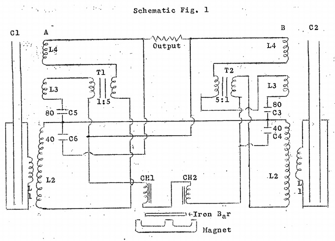
The unique feature of the Hendershot device is the basket weave coils, with cylindrical capacitors built in the center of the coils. (See A & B, Fig. 1) Hendershot did not explain his intent when he designed this part of the circuit. In the early days of his experience, during the late 20s, he used standard broadcast radio coils which he could purchase in the radio supply stores of that era.
A test of the present coil design on a radio frequency resonant bridge or “Q” meter will reveal that the coil out of the circuit will be self resonant in the lower frequency of the radio broadcast band of 500 KC. This indicates that Hendershot kept the present design in the same ratio of inductance that was used in the early days.
Another interesting component is the solenoid coils CH1 & CH2 used in conjunction with a magnet from a radar magnetron with a soft iron bar between the magnet and the solenoid coil cores. During operation of the Hendershot Fuelless Generator, this unit will buzz at a frequency rate dependent upon the air gap between the magnet, iron bar and coils.
The magnet-coil device was mounted in a frame so that a screw adjustment would move the coil in relation to the magnet, varying the air gap which varies the resonance of this “buzz” frequency. Like the basket weave coils, A & B, the magnet-coil device idea was derived from a telephone receiver used in the early days. A regular buzzer used in a door bell annunciator should serve the same purpose. Hendershot purchased the solenoid coils in a radio supply store and they appeared to have been used in a 110 volt bell ringer.
The two commercial transformers, also purchased from a radio supply store were vertical oscillator transformers used in a TV set and were of unknown make or brand. They have a 5:1 turns ratio. Hendershot used several different types of transformers in the circuit but found the TV ones worked the best. Two dual electrolytic capacitors C3, C4, C5 and C6 are standard Pyramid TM 58, 40-80 MFD at 450 working volts.
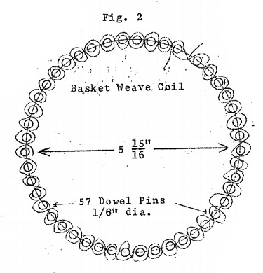
Two additional capacitors are required for C1 and C2. The hand-wound capacitor used in center of the basket weave coils are also made from Pyramids TM 58. Coils A & B are identical in construction so only one will be described. The coil is cylindrical, 5 15⁄16 in. diameter (See Fig. 2). It is wound like a basket around fifty-seven ⅛ in. diameter wood dowel pins three inches long. The dowel pins are even spaced on the circumference of the circle. All coils are wound in the same direction, weaving in and out between dowel pins mounted in the same type base to hold them rigid.
Starting at the base, L2 is 64 turns of No. 24 gauge copper enamel or Formvar wire close wound. L3 & L4 is Belden thermoplastic hookup wire No. 20 gauge, a 25 foot spool is required for each coil L3 and L4, 25 feet will end up with 24 turns wound in the same fashion as L2, close [20]wound. Hendershot always used L3 yellow and L4 red for easy identification.
L1 is made from No. 28 gauge copper enamel coated or Formvar magnet wire. 14 turns close wound over the outside diameter of L2 in the center of L2. Plastic electrical tape is wrapped around L1 to form a smooth surface for winding, after winding the 14 turns, wrap additional tape to hold L1 in place.
The Capacitors C1 & C2 are the most difficult to build and are the critical key item to success or failure in producing results. The foil from two capacitors, Pyramid electrolytic TM 58, must be removed from the can that encloses the foil by cutting the top or bottom off with a hack saw or other cutting device. The coiled foil is removed from two capacitors [21]and spread out on a flat table. A TM 58 capacitor should measure, including foil and paper, 91 ⅛ in. long and 2 ¾ in. wide. Wipe off-excess electrolytic solution so that it is dry. One side of the paper holding the foil will be full length, the opposite side will be split with terminal connections appearing at each end of the split portion. The capacitors that were used in the early experiments had a gap between the split foil of ¾ of an inch.
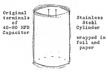
Prepare two cylinders of metal with dimensions of 5 ¼ in. in diameter by 2 ¾ inches wide. A stainless steel sheet metal .032 thick was used in Hendershot’s cylinders, open at both ends. Before wrapping begins, insulate the cylinders with pure kraft paper. Ordinary brown wrapping paper is unsatisfactory as it contains impurities. Wax paper might be used as a substitute.
It is interesting to note that Hendershot originally used one pound coffee cans for the capacitor cylinders but found that after a period of time the electrolytic left in the capacitor paper would perforations in the metal, rendering the cylinder useless. This is why he made the later cylinders of stainless steel.
After insulating the cylinders, wrap the capacitor foil and paper around each of the cylinders. Start at one end with the long unsplit foil on the inside and wrap the full length onto the cylinder. Secure the wrapped capacitor with a string or tape so that it will not unravel. Both units should now look the same.
Each of the completed capacitor cylinders C1 and C2 are placed on the inside diameter of Coil A and Coil B. After centering the cylinders, pour melted paraffin into the outside diameter of the cylinder and inside diameter of Coil A and Coil B. The melted paraffin will run into the turns of the wire sealing the complete units. If the correct tensions were applied while wrapping the capacitor paper and foil, the measured capacity should be .0078 MFD.
It is very difficult to obtain the correct capacity and this process may have to be repeated many times to arrive at the right value for each unit. Short circuits of the capacitor will render the results useless, and, of course, make it impossible to measure the resultant capacitance value. For accuracy the capacitors should be measured with a reliable capacitor bridge. Hendershot was able to accomplish this feat intuitively.
If all conditions of the circuit are met with the proper component values and if the wiring is made according to the schematic diagram, the unit should function and produce 300 to 500 watts of energy. The only limiting factor to the amount of power that can be extracted is the wire size used in the coils and transformers. Hendershot on many occasions [22]when applying excessive output loads, would burn up the unit by the over heating of the wiring. Some variations can be made in the circuit wiring but what changes are tolerable are unknown.
UNKNOWN CHARACTERISTICS
After a unit was wired either by Hendershot or other experimenters he would sit down at the device with a length of insulated wire bared at each end and begin making connections to various terminals of the unit until the solenoid magnet combination would buzz and the output load, if it was a standard 110 volt light bulb, would glow. He then would adjust the air gap between the magnet and solenoid coils until full brilliance was achieved and the buzzer produced a steady tone. This procedure would take from a few minutes to several hours.
On one occasion he adjusted the unit for 10 to 15 minutes and only achieved a flash of light from the output. Several hours later he found it necessary to rebuild the capacitors before any further tests could be made. Either the unit would work immediately or not at all, depending on the unknown characteristics of the phenomena.
It may be noted on the schematic that capacitor C6, which is one half of a dual Pyramid TM58, the positive terminal is connected to one side of the output load. This connection places an electrolytic capacitor in an AC circuit. A polarized capacitor will not work in an alternating field and will overheat. The schematic diagram as shown in Fig. 1 did operate for ten to fifteen minutes before the capacitor began to boil and blow out. If an experimenter should be fortunate enough to achieve success in producing power it may be advisable to connect this capacitor the same as C4.
Experimenters who have worked with Hendershot may have other circuit diagrams that also produced results, but this story has been this writer’s experience in a true story of Free Energy Phenomena.