Page 12 – Dealing with Rotor Induced Counter (Back) EMF – Update/March/2012
|
Recently, as I was going through some storage boxes, I came upon an old rotor and some air coil assemblies which had been destined for the junk heap years ago, but which somehow managed to escape their appointed fate. The rotor is bent and the magnets are poorly positioned, making the rotor severely out of balance. The rotor is made from a hardened aluminium alloy, and has 8 small (10mm diameter by 6mm deep) neodymium magnets embedded in a NSNS arrangement. The shaft bearings are badly worn, and the magnets are not really the optimum shape or size for use with the pancake air coils that the motor assembly uses. The hall sensor is hard glued to the assembly preventing adjustment of duty cycle (which is approximately 40%) and timing angle, but in spite of all these motor failings, it has performed well enough for the following presented experiments. First, some revision to put the experiments on this and following pages into context. On page 1- I wrote : – " the fast rotating magnets that sweep past the coil, also induce an ElectroMotive Force back into the coil which is in the opposite direction to the incoming supply current. This opposing direction of EMF is what is known as Back EMF and happens in all conventional motors regardless of motor type. " On page 2, I wrote the following: – "First I need to explain some things about Back EMP (BEMP) and Back Emf (BEMF). BEMP is Back Electromotive Potential while BEMF is Back Electromotive Force. What's the difference? Force is a measure of mass x acceleration. This implies that a movement of mass is an integral part of Force. In an electric circuit, this movement of mass is "current". Whilst there is a lot of debate about whether electrons actually move, or whether their electron "charge" is the only movement in the form of charge energy transfer from atom to atom, the notion of movement is still paramount to the formula of calculating force. For simplicity sake, we will assume that there is movement of some sort and leave it at that. So when we talk about BEMF, it is implied that there is a movement of charge which arises in opposition to the Forward EMF (FEMF supply current). BEMP is Back Electromotive Potential. In order for any BEMF to occur, there must be a BEMP, but the reverse is not always true. I will discuss Collapsing EMP (CEMP) and Collapsing EMF (CEMF) later on in following pages." |
|||||||||||||||||||||||||||||||||||
|
Below is a block diagram of two pulsed circuits. There are three possible types of EMF current flow that can manifest in a pulsed DC circuit. Clearly there is a major difference in the two circuits, even though they are used for the same function. The transistor circuit only shows Supply Forward EMF and Collapsing Field EMF (Flyback) because the transistor blocks any current flow (BEMF) from the opposite direction to the supply. But the Mosfet circuit, due to its conducting reverse body diode, provides a current path for Rotor Induced BEMF. This Rotor Induced BEMF is ever present in normal continuous DC motor circuits. |
|||||||||||||||||||||||||||||||||||

|
|||||||||||||||||||||||||||||||||||
|
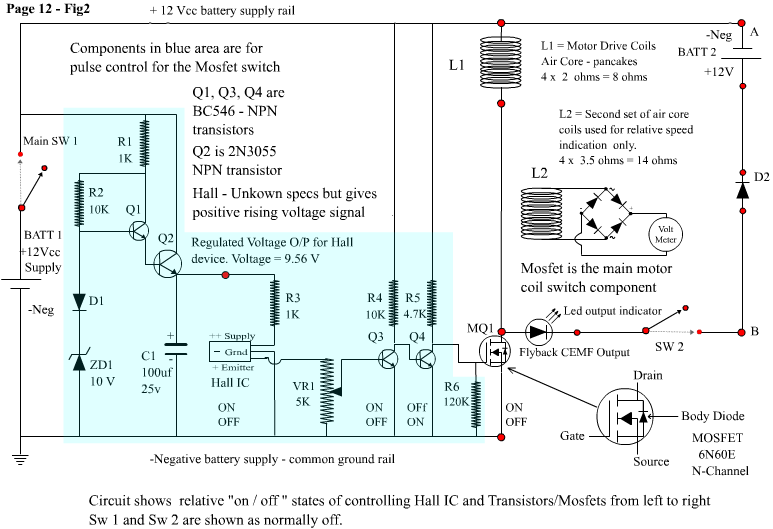
So what's the issue here ?. Is Rotor Induced BEMF in a DC motor a good or bad thing? Lets explore the idea. When I first started to learn about electric motors as an apprentice technician, the subject of BEMF with respect to continuous supply motors was presented. I remember my instructor saying that just because it (BEMF) is a force that emerges in opposite direction to the supply, doesn't necessarily mean its a negative thing. He explained that as the speed of a motor increases to working speed, the BEMF voltage arises in proportion to the motor speed and serves to limit the forward current by reducing the potential difference between the opposing voltages. At full running speed the two opposite electrical forces result in minimal forward current. Surely, that's a good thing ?. If you had to provide a constant high current to maintain your speed, electric motors would be very uneconomical. He also explained that the voltage of the back emf (rotor induced), never attains the same potential as that of the supply, which is why there always remains a certain amount of forward current to maintain speed. In fact, he explained that if the bemf voltage did equal that of the supply, the motor would begin to stall because there would no longer be any forward current to maintain rotation. He also informed us (his students) that the bemf cannot be stopped or diverted. We were guided through the various diagrams and explanations in our textbooks, and I believed him and the textbooks. It all seemed very logical and staightforward to me. So I filed that information into the "assumptions" folder in my head. That was a big mistake. I recently realized that this assumption may be erroneous with pulsed motors and it was time to investigate. The rest of this page is a presentation of circuits, data and information which challenges my filed away assumptions about back emf. What's presented here is probably only news to me! (and possibly some of you readers) LOL. For all I know, the information I've gleaned may have been common knowledge amongst EE professionals for decades. Below is the basic simple starting circuit I used for my first bemf experiment, showing all the main circuit components. It is a Mosfet switching circuit controlled by a Hall sensor connected to a fixed regulated voltage supply and intermediate fine tuning transistor "flip flop"output stage to the Mosfet. A LED is connected in the flyback circuit to give a visual indication of flyback current flow when the flyback circuit is engaged by operating SW2. It's not necessary, as the power diode D2 already serves it's main function, the LED is just convenient for visual confirmation. |
|||||||||||||||||||||||||||||||||||
|
|||||||||||||||||||||||||||||||||||
|
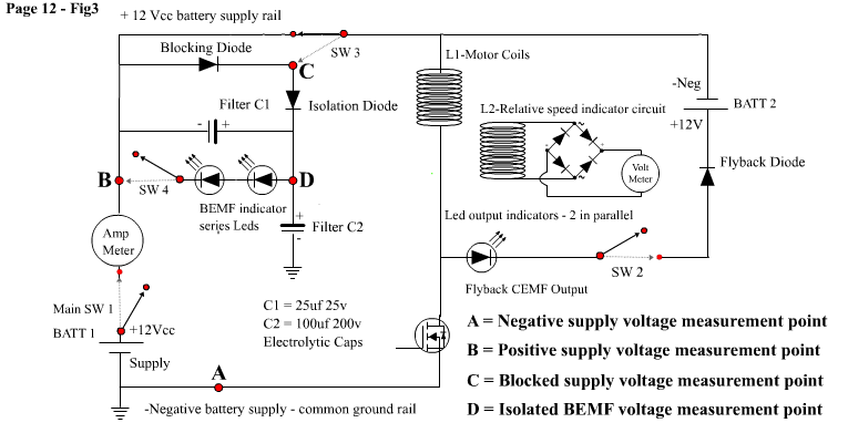
Below is a block diagram of the same circuit showing the introduction of a BEMF blocking diode, an isolating diode and some capacitors serving as a voltage ripple filter. This enables a more accurate BEMF voltage reading and redirection of the BEMF current (if there is any) through some series connected LEDS to the supply battery positive. Again, the LEDS are just for visual convenience to help show what's happening in the circuit. If the BEMF voltage never rises to a higher potential than the forward supply voltage then the blocking diode and all the other added components would prove to be of no use, requirement or benefit, and would also probably help to prove nothing at all in the experiments I've performed. LOL. Because I don't have a tachometer to measure rotor rpm, I have set up another 4 x series connected air coils on the opposite side of the motor, and have connected the output of these to a voltmeter via a full wave bridge. This at least gives me a visual relative rotor speed indicator, though I don't know the actual rpm of the rotor. |
|||||||||||||||||||||||||||||||||||
|
|||||||||||||||||||||||||||||||||||
|
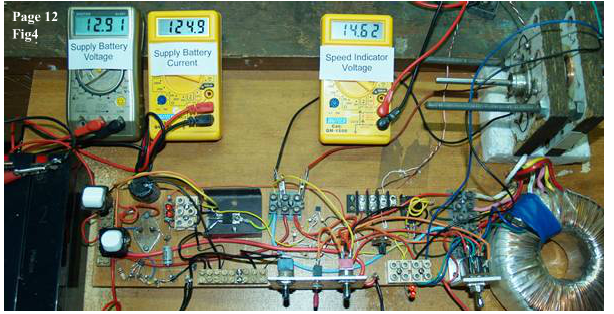
Below is a photo of my test rig. It is set up to allow for a number of different experiments. This photo below shows the basic device circuit running with only the main switch SW1 operated. There is no attempt to collect or divert the CEMF, and there is no blocking diode or other components in use to change the BEMF. The meters show the supply voltage, the supply current (in milliamps) and the relative speed voltage. |
|||||||||||||||||||||||||||||||||||
|
|||||||||||||||||||||||||||||||||||
|
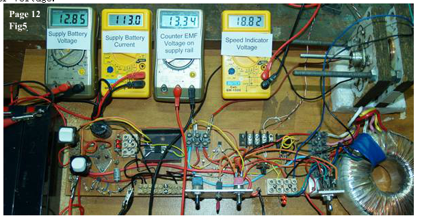
This photo shows the main switch SW1 operated and also SW3 operated, which puts the blocking diode in series with the supply rail. There is no attempt to collect or divert the CEMF, and the back emf is blocked only. There is no attempt to redirect or collect the bemf. The meters show the supply voltage (point B relative to point A), the supply current (in milliamps), the blocked supply rail voltage (point C relative to point A) and the relative speed indicator voltage. |
|||||||||||||||||||||||||||||||||||
|
|||||||||||||||||||||||||||||||||||
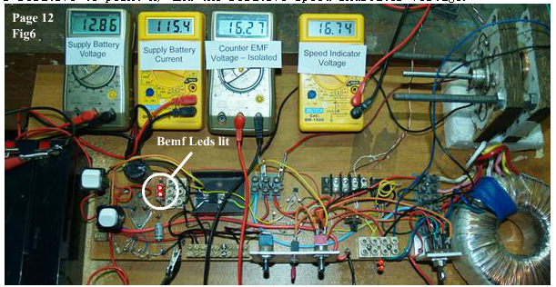
| This photo shows the main switch SW1 operated and also SW3 operated, which puts the blocking diode in series with the supply rail. It also shows SW4 operated which connects the Leds from the BEMF voltage to the positive of the supply. Note the Leds are lit. There is no attempt to collect or divert the CEMF. The meters show the supply voltage (point B relative to point A), the supply current (in milliamps), the isolated BEMF (Counter emf) voltage (point D relative to point A) and the relative speed indicator voltage. | |||||||||||||||||||||||||||||||||||
|
|||||||||||||||||||||||||||||||||||
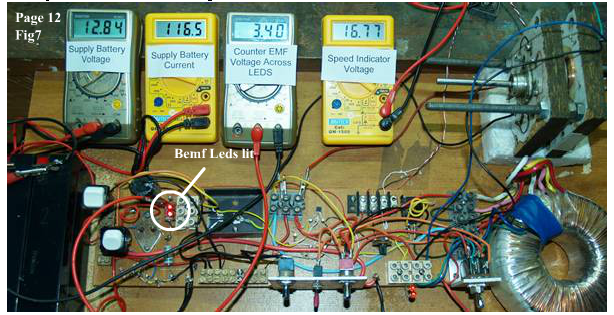
| This photo also shows the main switch SW1, SW3 and SW4 operated. There is no attempt to collect or divert the CEMF. The meters show the supply voltage (point B relative to point A), the supply current (in milliamps), the isolated BEMF (Counter emf) voltage across the Leds (point D relative to point B) and the relative speed indicator voltage. | |||||||||||||||||||||||||||||||||||
|
|||||||||||||||||||||||||||||||||||
|
In the photos above, note that Fig5,Fig6 and Fig7 show a reduction in current consumption and an increased rotor speed compared to Fig4 which has no blocking diode in the circuit. Fig5 in particular, which has only the blocking diode in circuit, shows the greatest current reduction and the highest speed increase. Also please note that the difference in the supply voltage in Fig4 compared to the Figs5,6,and 7 is largely due to the battery losing some surface charge after running for a few minutes, before settling into its running voltage. So far, that's two of my "assumptions" discarded, with respect to pulsed motors. BEMF voltage can and does rise beyond the supply voltage. In doing so, however, "with this particular motor", it is counter productive to torque and efficiency. However, it can easily be blocked. If I had used switching Transistors, it would already be blocked, but by using switching Mosfets (with a body diode), it is not be blocked. If the bemf is blocked with a diode, it can be diverted, as shown by the lighted Leds in series with the battery return path. In this pulsed system BEMF is not required as a supply current limiter, because the increased initial current from the supply in the absence of bemf, is offset by the increased speed that the motor attains. The current is then is limited by the increased inductive reactance of the coils due to higher frequency (rpm – speed). This can be observed on the meters, when the motor is already running without the blocking diode, then the blocking diode is switched into circuit. There is an initial increase in supply current as soon as the switch is operated, then the motor responds by increasing it's rpm (higher running torque), while the current reduces (higher effiency) to a level lower than previously, without the blocking diode. Inversely, however, as soon as I switched the bemf LEDS into the circuit, this allowed some of the bemf current to flow to the battery. That initially resulted in a slight decrease of current, but was followed by a slight decrease in rpm (counter productive to torque), and then a slight increase in supply current (lower efficiency) above the previous level, as the motor speed decreased. The meter readings as shown in the table below reveal that even a small amount of bemf current into the battery such as that through the Leds, can result in a lowering of motor efficiency.
|
|||||||||||||||||||||||||||||||||||
|
|||||||||||||||||||||||||||||||||||
|
See Page13 for more information and additional experimental data. |