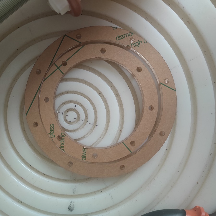
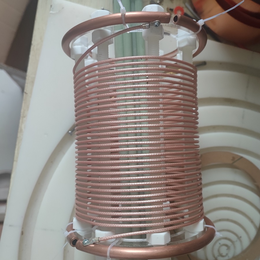
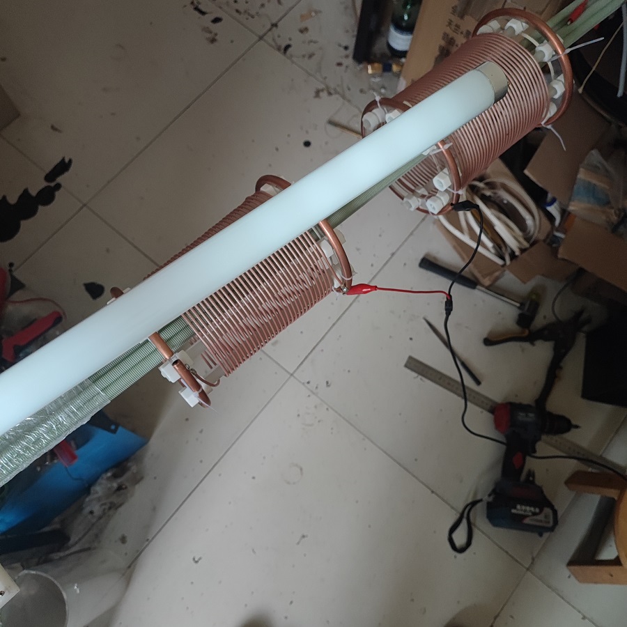
我的线圈直径是120mm,高度150mm,使用的电线是RG316,相当于直径2.5mm的电线。线与线的间距大约是4.5-2.8=1.7mm。螺杆是10mm的环氧树脂纤维材料,螺帽是PP材料的。两端的圆形骨架是亚克力材料,共计8个10mm的孔,外径是125mm。铜管是8mm,开口距离大概是10mm。线圈的圈数是31圈。
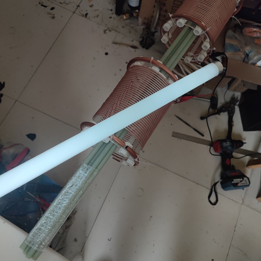
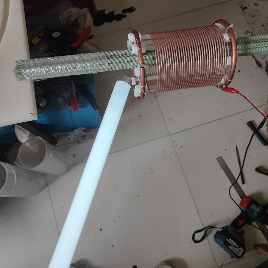
注意点:因为我制作的是两个线圈,刚开始两个线圈的圈数有轻微的误差,大概1/5圈左右,造成两个线圈的共振频率偏差100khz左右。
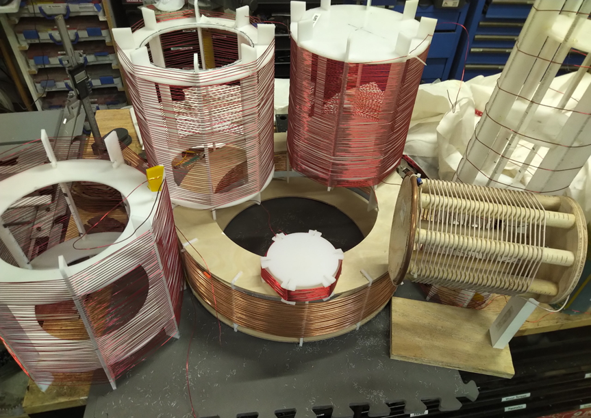
线面是一些照片。实验时候使用的频率是6.96MHZ。电压大约是28VPP。注意VPP表示峰峰值。
下面是国外网友的制作教程。
Preparations
Starting guide: wind a coil with a height-diameter ratio around 1:1 with an air-gap between turns of at least half the wire diameter.
or:
297/F = L
F = frequency in Mhz
L = wire length in feet
Note that due to dielectric effects, a Tesla Extra coil has a higher frequency than is predicted by normal 1/4 wavelength formulas. We call this the ‘velocity factor’ and it is directly related to the height-to-width ratio of the coil.
Framing Material Selection
- Best: UHMW, HDPE, LDPE, PTFE(Teflon), PP
- OK: Polystyrene
- Meh: Polycarbonate, Acrylic, Epoxies, PVC, Wood
- 3/16″ to 1/4″ thickness works good for coils 3-12in in diameter
- Plastic sheeting is usually sized in 12×12″ sections, so cost-efficient diameters are around 5-5.5″ and 11-11.5″
- White/light plastic have lower loss characteristics
- Material selection has a higher impact at higher frequencies
-
Wire selection:
The general goal here is to get the lowest resistance practical.
Obviously few people can afford 100ft of 0 gauge copper bus-bar to wind a coil, so compromises must be made. Generally we recommend not going below 20awg though as the loss characteristics begin to compound making a very high Q coil difficult to achieve.
- Silver-coated Teflon wire
- Silicone-coated wire
- Litz wire
- Coax cable can also be used to create a large effective diameter coil by using the outer ground conductor (per Eric Dollard)
- Coax cabling can also be used to create a large effective diameter coil by using the outer ground conductor (per Eric Dollard)
-
Construction
‘Jigsaw method’

Cheapest/simplest tools required:
- Drill + drillbit set
- Jigsaw / router / hand saw
- Hand files


Cutting the top+bottom disks. Best practice is to use a circle-cutting jig on a jigsaw/router, but many techniques could be used to do this. 
Notching the disks. Notch width = thickness of your material. Depth is not critical but should be at least 2x the thickness of the notch. 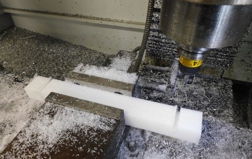
Notching+grooving the vertical risers. This is the best time to cut the wire grooves, which can be done with a hand saw in a pinch. 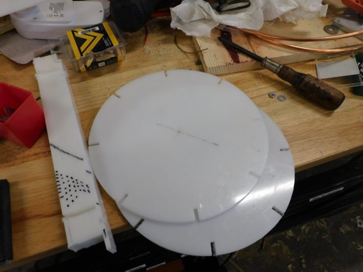

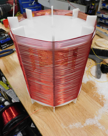
Now you’ve finished your first Tesla Coil. What do I do with it?
Testing and Tuning (coming soon)
6 responses to “Build a Tesla Coil (the way Tesla built them)”
Now that I can make the described coil, what else do I need to have a compact power supply?
For testing you can use a function generator or HAM radio transmitter (if it is on the right frequency).
The most efficient power supply would be a class E amplifier, which would look like this:
https://www.researchgate.net/figure/Schematic-of-69MHz-Class-E-amplifier_fig2_320623200
The inductor on the right would be your Tesla Extra coil,
instead of a filter cap and resistor you would have a bridge rectifier and capacitor filter.
Feel free to email me @ bakahsay@gmail.com or discord @ Hakasays#7694 and I can try to help you get something together.
Hi Hakasays (I don’t know your name). I am utilizing your TeslaCoilCalculator to build my first tesla coil. There are two spacing parameters listed in the output: Wire Spacing and Ideal Wire Spacing. The Ideal Wire Spacing is much closer than the Wire Spacing parameter. Which parameter should I use to wind my coil?
Where are the detailed calculations for the calculator output stored? May I have access to these formulas and the associated references?
Thanks and have a great day,
Breck.
The equations were pulled from Eric Dollard’s “crystal radio initiative” project, which I believe is an Ebook and a couple videos.
Some useful bits here: https://kupdf.net/download/crystal-radio-initiative_5af89140e2b6f5131fd54e23_pdf
Ideal wire spacing is 62% of the wire diameter. So a 1mm wire would be 1.62mm from center-to-center. (Wire spacing has a bug that I haven’t patched-out yet, sorry about that)
I do intend on posting the formulas driving the calculator online at some point, just been busy with other side-projects like the telluric work.
Hi
I tried winding a coil over a normal mailing tube instead of plastic chassis, with quarter wave length (approx 4m). I connected the positive end of function generator to the bottom end of the coil and the negative end left free.
But unfortunately even changing frequency +- many times, I failed to establish any standing wave with resonance.
Is it good to connect the signal generator directly or any amplifier needed?
just seen your video presentation and it fills me with a new hope that an original design will allow the magic we are looking for. I will post me example and results. I have made various experiments with the bifilar coils and i beleive this will give us what we are looking for. It could also give us the power needed to replemish the run battery or capacitors?