Page 10 : An Experiment in Bending "Lenz's Law"
|
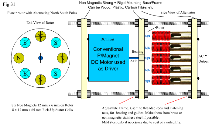
This is a simple and straighforward experiment, but because of the high torque and speeds involved, YOU will have to build an alternator And for YOUR safety, YOUR rotor, bearings, framework and axle should be made as precisely and well balanced as possible. The materials you choose to make your rotor and frame should be solid and sturdy, and heat resistant. All care should be taken to centre align the drive motor and alternator shafts. All safety precautions should be exercised, before running the combination motor driver and alternator as shown in Fig 31 below. At the end of the page is a Printable Template of the frames and rotor which is scaled (true size) for use in this experiment. You will need to source 3 identical 12 Volt DC Permanent Magnet or DC Shunt Wound Motor/s. Whew! sounds hard – easy really. they're common as snails! You can get away with a minimum of 2 DC motors, but with three DC motors, the experiment is set up more easily, and offers comparisons of differing reactions in real time. |
|
|
|
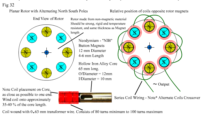
Fig 31 Above shows a planar rotor open magnetic systen alternator with 8 hollow cores (not all cores are shown), each core wound with 80-100 turns of 0.63 mm transformer wire. They are low impedance coils. The alternator is driven by an ordinary 12 Volts DC High Torque Permanent Magnet or DC Shunt Wound Motor. The perfect sizes and power ranges of the DC motor for this experiment are commonly found in good quality 12 Volt Cordless Power Drills. They are not very large, but they "pack a lot of throttle"! Common sizes range from 25-40 mm in diameter and 45-60 mm long. They can endure short periods of high current up to 10 amps, and will run nominally on 3 -4 Amps under a moderate load for a reasonable time. They are perfect for this experiment because it shouldn't take that long! The motors are cheap, easy to source, high speed and powerful for their size. Not only are their torque characteristics good, but, because they are DC and Shielded, any "peculiar effects" noticed in your experiment willnot be falsely attributed to any "Pulsing Current" or "Pulsing Voltage". Not-withstanding any voltage peaks introduced, if the brushes of the DC motor are exremely worn, and you are using Digital Meters. Other than that, the current supply will be straight, clean DC Especially if you use a 12Volt Battery for your supply. With no "Adams Motor" or other pulsing mechanism in sight, You will prove in this experiment that Lenz's Law can be "bent" by ordinary AC with any "open magnetic system", and this "bending" does not rely on pulsing currents or pulsing voltage in any way. Fig 32 below shows how the alternator coils should be wired. Note that 4 coils have the wires crossed over and 4 do not. This is an alternator and the coils must be equal to and sychronous with the alternating rotor magnet poles. This is an ordinary AC coil arrangement! |
|
|
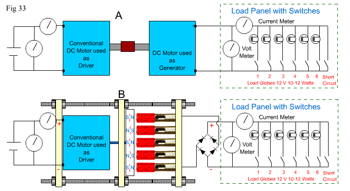
Remember the experiment on page 8 Figs 24 and 25? comparing a DC generator output with the Rectified output of the Adams Pick-up coils. We compared the differences in the "breaking effect" of an open and closed magnetic system. And if things went right for you, you noticed a "strange effect" with the open magnetic system. This following experiment is meant to exaggerate that effect, so that it is undeniable and unmistakable. The key factors here are torque and speed. And hence"frequency"! Well here's the experiment again, with Fig 33 Below, except there is now an ordinary motor, driving the open magnetic system alternator. The alternator is a "true" alternator with an alternating North and South pole rotor, and alternately connected pick-up coils. The Resistor Load Panel has been replaced with an Incandescent Globe Panel. The Globe Panel does exactly the same thing as the Resistor Panel, but looks more Spectacular! (LOL)! Each globe has a measurable DC resistance of approximately 12 ohms. So thats 12 V / 12 Ohms = 1 amp per globe. Max globe power at 12 V = 12 V x 1 amp = 12 watts. Typical Automobile Globes from anywhere.You can use either sort of Load Panel as the result will be the same in both cases. |
|
|
|
In the experiment on page 8 was Fig 24 with a subsequent explanation. It's repeated below, with edits, with the reference now relating to Group A in Fig 33 above: " when motor A is connected to the supply, it turns motor B by common coupling at the shafts of each motor. Motor B is generating a Voltage produced by the Torque from Motor A, so we'll refer to Motor B as the Generator. The output Voltage from the Generator will not be quite as high as the input voltage to Motor A because of transference losses. All load switches are open and there is no load on the generator, so both the motor and generator will turn readily together at a high speed. But as soon as you close the switch to R1/Globe1, the generator circuit will provide current to the resistor, and this will cause a breaking effect due to Lenz's Law. This will cause the motor to slow down a bit because it has to work harder to maintain RPM against the oppositon created by the generator. Now switch on R2, then R3, R4, R5, R6, until you switch on the short circuit at the end of the generator output line. Each time you switch on another Resistor/Globe, the breaking effect due to Lenz's Law will increase with increased current (shown by the current meter). At short circuit, the breaking effect within the generator will become so great that it will cause Motor A to stall and start "smoking" if you leave it connected too long! . As the breaking effect takes place you will see the supply current increase dramatically with each increase in load, as Motor A works harder to achieve continued rotation." Then on Page 8 was Fig 25 with a subsequent explanation. It's repeated below, with edits, with the reference now relating to Group B in Fig 33 above: "the pick-up coils are connected via a full wave bridge to the Load Panel for both measurement purposes and to compare like with like. The experiment with the two DC motors produces DC output because the DC motor coils are connected via commutator switches. So we'll rectify and make the alternator output DC as well. Now repeat the previous experiment. Be aware you are not trying to create a true comparison between the DC motors and your alternator per se, but a comparison in the way Lenz's Law affects or doesn't affect them. Turn on the supply to your alternators DC drive motor, let the whole assembly reach top speed, then start switching the load Resistors/Globes on, one by one, from R1/Globe1 to the Short Circuit. To repeat what should be : "According to Lenz's Law, you should perceive a slowing of the rotor because the current induced into the coils opposes the movement of the rotor." What actually happens ?????. If your alternator is operating within the "realm of disbelief", as it likely will (LOL), you will notice something very strange!!.
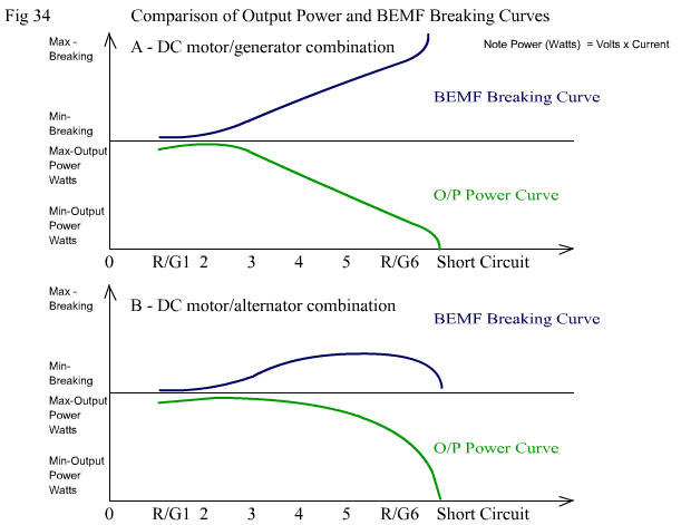
You may notice the following: Now this is what I have personally observed in countless experiments and numerous different open magnetic alternating systems. Replicate it Please !!!!" " See Fig 34 below and the explanation of the benefit of this "bending" effect. |
|
|
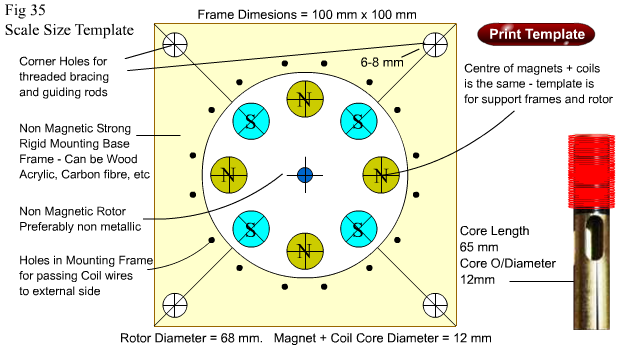
The ramifications of the effect produced in this experiment are not obvious at first, until you do the experiment and take actual input and output voltages and current readings. The load panels are designed to give you an indication of true DC power output, because it is necessary to measure current through a load and the voltage across that same load at the same time. P = E x I. By taking current and voltage measurements of both the driving motor, and the generator/alternator outputs, you can plot an input and output power curve for both Groups A and B.When you see the power curves, you'll notice that the alternator maintains a higher usable electrical power output for a much greater load demand. And it produces minimal breaking effect when short circuited to the extent that, it acts like an open circuit. If you do an Input Power Curve for each group you will see that the Input Power Curve for Group A will rise almost linearly like its BEMF does in Fig 34 A. But you'll notice for Group B that the Input Power Curve will look like the BEMF curve in Fig 34 B. It will rise at first, then it will curve back down – almost to the level it started before any load was placed on the coils!!! So, with short circuited output, you will be using no more power than open circuit output. With Group A, a short circuit is catastrophic. With Group B, it's a minor nuisance. Because there is almost zero "breaking effect" at short circuit, there is minimal drag on the driver motor, and it will maintain a higher RPM than if it were under slight load !! Below is a Printable Scaled Template for use in drilling, aligning etc, if you wish to make your own alternator based on the one shown above. |
|
|
The 64 million dollar question, is, Why and how does this effect occur?? See Page 11 for an explanation I have given you all the little pointers you need to exaggerate and see this effect for yourself, and know that Adams really did discover something useful and have something to offer, even if it wasn't really what he thought it was. But hey, a really easy to make alternator, that outstrips conventional induction means of generation whilst using less iron and copper is something special isn't it ? Sure can help to save a lot of money all round. Wind generators would really benefit from this type of generating system. Now"bend" those power and bemf curves – yeh! Happy experimenting to all ! |