Page 9 : Controlling Duty Cycle and the advantage of using Optical Switching versus Hall Switching
|
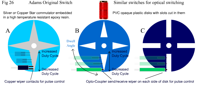
When Robert Adams first introduced his motor to the world he also introduced a very unique but simple switch in the form of a metal star shape embedded in a disk. It was a mechanical switching system, which he later used to control a power transistor. See Fig 26 below. |
|
|
|
Fig 26 above shows Adams Original Star Switch Disk . The metal switching disk was mounted onto the shaft of the rotor, and would spin in unison with the rotor. There were associated copper wiper contacts to produce a pulse. Initially he controlled his drive coils directly with these contacts, but due to sparking problems which caused contact failure and commutator damage, he later used the switch to control a transistor, which in turn controlled the drive coils. By connecting the supply via the contacts to the base of the transistor through a 470 ohm resistor, the contacts switched less current, while the transistor switched the main drive current, the sparking of the contacts became less pronounced, and damage to the commutator and contacts was minimal. The actual design of the switch is classic KISS, and works perfectly for tuning or varying the dwell angle and duty cycle to any one desired. The Designs B and C replicate this design, but are simply made from opaque PVC sheet about 2-4 mm thick. Instead of using copper contacts on the same side of the disk, the contacts are subsituted with a sender (LED) and a receiver (photo sensitive:- transistor or diode or resistor). The sender is placed on one side of the disk while the receiver is placed on the other side. In this way, as the disk spins with the rotor, the disk will block the light (photon) path of the send / receive pair, or allow the light path through the slots or triangles which are cut into the disk. Disk B mimics Adams disk completely, except that it is imposible to overshoot the duty cycle above 50 %. Disk C works just as effectively, though its controllable duty cycle cannot go as low as A or B (in the dimensions shown). It is just much easier to make than A or B, and provided the slots are not too wide or too long you will achieve a desirable duty cycle range from approx 10% to 50%. To allow lower duty cycles make the slots narrower, to allow higher duty cycles make them longer (or wider, or both). Remember anything above 50% is counterproductive. You can see that by moving the contacts up or down towards the centre of the disks or to the outer edge, you will vary the ratio of "on" time versus "off" time. That is, you will control the duty cycle. By changing the placement of the contacts around the circumference of the disk, you will change the dwell angle. This type of design gives very precise control over both switching parameters and is recommended for experimenters who want or require flexibility for both parameters. The advantage of using Optical Switching over mechanical switching is there are no sparks and no physical fatigue on the control sensors. The opto-switching method offers a more precise and flexible control over switching parameters easily. A Hall IC is not as precise, and although you can vary dwell angle easily, you can not increase duty cycle easily, or lower duty cycle precisely! In Fig 27 below we look at duty cycle and how it is affected by "Time Constants". Hopefully you read some of the material regarding "Time Constants" that I provided links to at the bottom of page 7 and are a little bit familiar now with the concept. See below Fig 27 for an explanation of the circuit differences. |
|
|
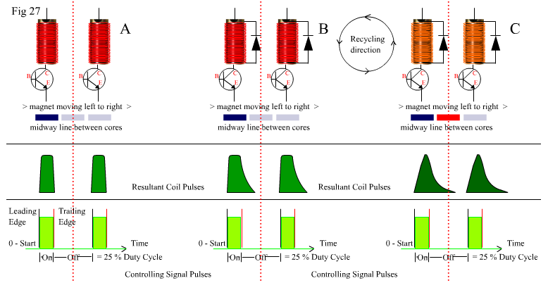
In Fig 27 above there are 3 groups of 2 coils, A, B and C. The distance between the middle of these sets of two coils represents the Total Pulse Cycle. From the first pulse to the next pulse, etc.. Between these two coils is the mid way point of travel of the rotor magnet/s moving according to the pulse. Group A represents two "low impedance" coils which are used in drive mode only. There is no re-circulating path for the CEMF via a diode, so there is no recycling of current. Looking at Fig 27 you will see that at the bottom of each group, there is a light green square current pulse labeled "Controlling Signal Pulses". This is the desired shape of your signal to the base / gate of your drive transistor / mosfet. Notice how above them is a series of pulse shapes labeled "Resultant Coil Pulses". These are the current pulse shapes actually formed in the coils according to the actual "Time Constants" of the circuit. They are the "Virtual Duty Cycle" of the motor.
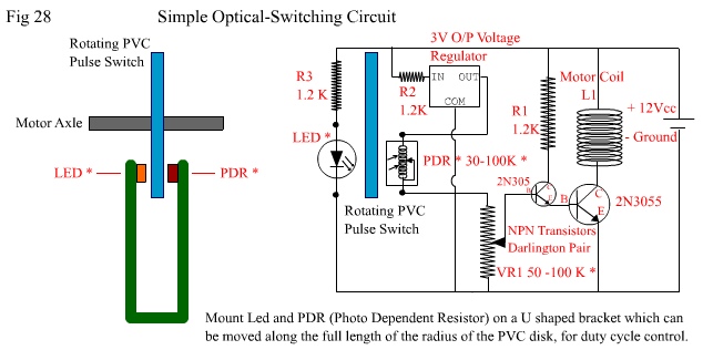
Regarding Resultant Coil Pulses. In Group B the same "low impedance" coils have a diode across them, so when the signal pulse is off, the CEMP in the drive coil/s creates CEMF which flows via the diode/s in a circulatory path back through the drive inductor/s. The leading edge of the pulse in Group B is the same shape as Group A but the trailing edge of the current is extended in time because of the recirculating current. Think of the coil/s and diode/s together forming a unidirectional resonant "ringing bell which takes a while to subside". By the time the magnet reaches the middle passover point, however, the "ringing" current has subsided and the cores are no longer active, and the magnet is now in attraction mode to the next core. In Group C the coils are "high impedance". They are made with larger cores, and have many more turns, giving them much higher inductance and resistance. The resultant drive pulse shape is nothing like the signal shape. It takes almost the entire length of the signal pulse for the drive voltage and current in the inductor to reach maximum. Then with the collapsing edge of the signal pulse, the drive current recirculation via the diode causes the magnetic field to collapse VERY slowly. If the time it takes is too long, then the core will still be inducing a repeling force on the magnet as it passes the middle crossover point. You can see in Group C that the red magnet is ready to move forward into what should be an attraction zone, but the core it should be moving toward would still be partially active and will be in repelling mode. This will cause torque and energy loss. In Group C you can see why the ability to precisely control the length of the signal pulses is important. Especially when utilizing the recirculating current. Even more so when using high impendance coils. The circuitry that allows a recirculating current, also creates a "Time Constant" which is dependant on the Resistive and Inductive values of the coils themselves, and / or loads, which are in series with the regenerative loop thats produced. This "Time Constant" has a dynamic feedback effect on the actual duty cycle, producing instead a "Resultant Virtual Duty Cycle". As always, theres "No Punch without Judy"!. But with careful design, you can exploit this extended pulse time, as long as your resultant duty cycle pulse is no more than 50 % of the real total cycle. See Fig 28 below for a simplified layout of a photo-controlled switching circuit. |
|
|
|
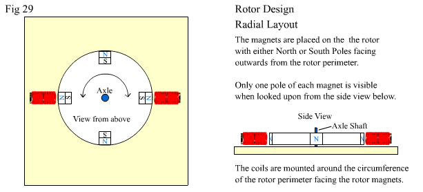
In Fig 28 above, the pulsing signal is produced by a PVC disk with slots cut into it, rotating between a LED (Light Emiting Diode) and a Photo Dependent Resistor. When the LED shines through the slot of the PVC disk, the resistance of the Photo Dependent Resistor changes from 100 k-ohm to around 30 k-ohms. This will raise the bias voltage to the Darlington Pair of Transistors, and they will turn on and deliver current to the motor coil. Note the inclusion of a 3 V Voltage regulator to keep the signal supply voltage steady at all times. Variable resistor VR1 is included to give fine tuning to the bias of the Darlington Pair to ensure that the Darlington Pair turn off completely when they need to. The actual maximum value of VR1 is to some degree, dependent on the maximum and minimum resistances of the PDR. Now we'll briefly discuss rotor design. See Fig 29 below. |
|
|
Fig 29 above shows a very simple beginners layout for an Adams motor. Its a typical Radial Design. It's a good design to start with as you learn the basics of operation. But it has a number of limitations, and can pose safety problems. In the above diagram, if the supply was 24-48 Volts, and the drive coils were low impedance coils (1-2 ohms), then the rotor would easily reach speeds between 5,000 to 10,000 RPM. At these speeds, the centrifigal force on the magnets can be so great, that there is a great risk of the magnets flying off the rotor if they are not bound to the rotor very well. The magnets can be very dangerous if they fly off, and will easily cause serious injury. Other limitations include: limited number of coils you can place around the rotor whilst trying to keep the whole motor within respectable size limits, and only having access to one side of the magnet. In Fig 30 below we look at a Planar Design. See below for explanation. |
|
|
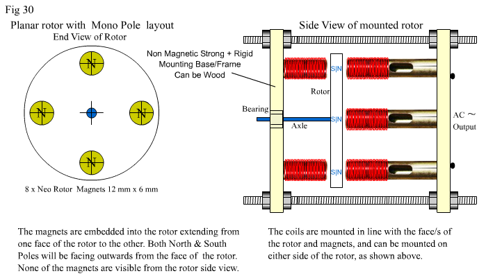
Fig 30 above shows the rotor layout in a different manner. It shows the magnets inserted into the face of the rotor instead of the circumference or outer edge of the rotor. The magnet length and rotor thickness should be matched, to minimize wind drag and maximize safety. The rotor can be made from plastics, resins, or wood or even aluminium (O.K. but not recommended ). High temperature epoxy resin, or a thermo-hardening plastic is best if you're confident with moulding it, and lathing it smooth afterwoods. The magnets are inset from the edge of the rotor, thus providing the magnet with a solid barrier of outer rotor material, preventing it from flying off when the rotor is spinning at high speeds. It is a slightly more difficult design to set-up, often requiring two bearings instead of just one, and two (or more) mounting plates, but it is much safer when designing high powered, high speed rotors. It also has the advantage of allowing access to both sides of the magnets, which can increase greatly the total number of coil configurations used for a particular setup. It is also easy to have multiple rotor disks on the same axle shaft, with 2 disks interacting with single drive cores between them. Why not 3 or 4 rotor disks? It's entirely up to you and how powerful a machine you want to build. Note * Adjustment of the distance between the magnets and the cores in a planar design can be a little more difficult than in a radial design, but can be facilitated using 4 long threaded non-magnetic stainless steel or brass rods and nuts as adjustable frame guides. Soft Iron or Galvanised threaded rods will do, but will affect the rotor by proximity to it, because they are magnetically reactive metals. Same applies to your axle. Use something non-magnetic if possible. For most experiments, it will NOT BE CRITICAL to the success or failure of the experiment.. In Fig 31 on the following page, is presented a very simple experiment you can do to "Bend Lenz's Law" using an "open magnetic system" alternator (which you build yourself) driven by a conventional closed magnetic system DC motor.(which you dont need to build yourself!) (LOL). I hope this general information and that on preceding pages has been of some help to you, the experimenter, and has not left you more confused than enlightened! This is the last page dealing with Adams Pulsed Motors…….. Happy motoring pulsars, I hope you discover what you think you're looking for. Keep Experimenting! |