Page 8 : Pick-up Coils and Bending Lenz's Law
|
Please don't take a single word I have to say on this page as explicit "truth ". PLEASE reproduce your own motor/generator experiments as outlined on this page. Please Verify Effects For Yourself!!! Hopefully you've already digested some of the complicated stuff, and in keeping with the KISS principle, you've decided to stick with single wound drive coils for the time being and see what single wound "pick-up coils" can do. They are a so called "passive" component of the circuit , so it should be straight forward to set them up and use them, shouldn't it ???. Yeah right! The accepted theory says: place a pick-up coil near the rotor and hook up a full wave bridge to it, and wallah! instant DC power, but with a price. The price is due to Lenz's Law as it applies to generators.
Lenz's Law states that: the magnetic field of any induced current opposes the change that induces it. That means the moment you start using any current from your pick-up coils, that same current will oppose the motion of the magnets! That's whatLenz says. So much for being passive coils! Now in almost all instances I would pay complete homage to a great man like Lenz and agree with everything he says. How dare I say it, but, in the instance of an "open magnetic system" he is only partly correct!. He is not wrong, he's just not completely right. Lenz's Law probably needs a little post editing to say " the magnetic field of most induced current opposes the change that induces it, most of the time ". Whew!, I'm really going to get into trouble with the "establishment" over that statement. I only changed one word and added a few more, but it's a BIG change for the parameters of motor/generator construction. You've already seen how the circuit in Fig 19 on page 6 can redirect an oppositional current to a complimentary unidirectional one, thus aiding the inducing force instead of opposing it. So you've already seen a principle at work in pulsing which "bends" Lenz's Law. Try the bi-filar arrangement in Fig 19 yourself! Keep impedances low, under 5 ohms, and duty cycle to 25% or less. But even a so called "passive" coil, which is one that is not connected to any power supply, will bend Lenz's Law in an open magnetic system You will be able to prove this yourself because Robert Adams the inventor of the Adams motor published a complete simple coil and rotor layout diagram for you already.. Unfortunately, Robert Adams misinterpreted what it revealed to himself. I believe that he was no fraud, and "he honestly believed" that extra energy was entering into the system, when in fact there was less out of phase "oppositional" energy created which hinders a motor system. You can prove this yourself, if you do a few experiments. Adams shows you how to bend Lenz's Law in Fig 23 below. |
|
|
|
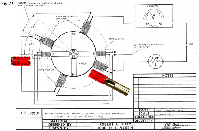
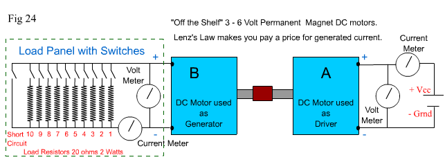
Fig 23 above, shows Robert Adams now famous "Golden Ratio Motor Generator". Superimposed , are two pictures of unconnected coils simply to draw attention to the coils in Adams original diagram. You will notice that his pick-up coils have a "heel end". And his drive coils do not. I explained this difference in core usage and operation on Page 4 / Fig 11. Don't argue with Adams on this feature. What I hadn't previously explained, was that the "heel end" also exaggerates the effect you will create. You may also notice that in Adams diagram he shows an "Ammeter" for measuring current, yet on his ammeter is the ~ symbol which represents AC. There has never been an analogue meter built, which can measure AC current directly, so we'll have to assume that the meter has it's own inbuilt full wave bridge to convert the current to DC. Always question what you see! Now, assuming you've got all the ingredients to make a motor.- What's important in this experiment is that your motor has plenty of real torque, so use quite low impedance coils for your drive. Approximately 150-200 turns of .6 mm wire for each drive coil on a core approximately 50-60 mm long and about 10-12 mm in diameter. Preferably use hollow cores if you can, because they also exaggerate the effect and minimize drag. But if you're an Adams purist, then make your drive cores from non-retentive magnetic stainless steel and use laminated soft iron for your pick-up cores. You will want a slightly higher voltage output than the supply, but still want a reasonable current from your output coils, so wind approx 200 – 300 turns of the same .6 mm wire on a core which is approx 70-100 mm long and 10-12 mm diameter. According to Adams diagram, connect the 2 drive coils in series, and the 4 pick-up coils in series also. Your rotor will probably be somewhere between 80 – 140 mm diameter, and you're probably using neodymium magnets which are around 10-15 mm diameter and 10-15 mm length. Desired rotor size, core lengths, diameters etc are"Not Critical". You just want your motor to have plenty of "grunt – real torque" so that it still spins at quite a high RPM after you have placed your "heel end" pick-up coils into position. In Adams original description of this circuit, he claimed that "when you connect the output of the pickup coils to a load, the torque of the motor will increase". Why would he claim that? What happens when you connect the output to a load?. According to Lenz's Law, you shouldperceive a slowing of the rotor because the current induced into the coils opposes the movement of the rotor. To understand the effect in an Adams motor, lets quickly prove that Lenz is ordinarily right, with a motor / generator that completely obeys his laws. You will need two small conventional DC permanent magnet motors. They don't have to be identical, but identical is better. See Fig 24 below. |
|
|
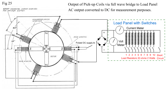
In Fig 24 above when motor A is connected to the supply, it turns motor B by common coupling at the shafts of each motor. Motor B is generating a Voltage produced by the Torque from Motor A, so we'll refer to Motor B as the Generator. The output Voltage from the Generator will not be quite as high as the input voltage to Motor A because of transference losses. All load switches are open and there is no load on the generator, so both the motor and generator will turn readily together at a high speed. But as soon as you close the switch to R1, the generator circuit will provide current to the resistor, and this will cause a breaking effect due to Lenz's Law. This will cause the motor to slow down a bit because it has to work harder to maintain RPM against the oppositon created by the generator. Now switch on R2, then R3, R4, R5, R6, etc, until you switch on the short circuit at the end of the generator output line. Each time you switch on another Resistor, the breaking effect due to Lenz's Law will increase with increased current (shown by the current meter). At short circuit, the breaking effect within the generator will become so great that it will cause Motor A to stall and start "smoking" if you leave it connected too long! . As the breaking effect takes place you will see the supply current increase dramatically with each increase in load, as Motor A works harder to achieve continued rotation. Now connect the Load Panel shown in Fig 24 above to the output of your Adams motor "Pick-Up Coils" as shown in Fig 25 Below. (Make your own Load Panel if you need to, and note meters are optional but recommended for this experiment.) |
|
|
|
In Fig 25 the Adams motor pick-up coils are connected via a full wave bridge to the Load Panel for both measurement purposes and to compare like with like. The experiment with the two DC motors produces DC output because the DC motor coils are connected via commutator switches. So we'll make the Adams motor/generator output DC as well. Now repeat the previous experiment. Be aware you are not trying to create a true comparison between the DC motors and an Adams motor per se, but a comparison in the way Lenz's Law affects or doesn't affect them. Turn on the supply to your Adams motor, let it get to top speed, then start switching the load Resistors on, one by one, from R1 to the Short Circuit. To repeat what should be : "According to Lenz's Law, you should perceive a slowing of the rotor because the current induced into the coils opposes the movement of the rotor." What actually happens ?????. If your motor is operating within the "realm of disbelief", as it likely will (LOL), you will notice something very strange!!.
You may notice the following: Now this is what I have personally observed in countless experiments and numerous different Adams motor Configurations. Replicate it Please !!!! Don't be discouraged if your coil setup doesn't do this. Try connecting the 4 coils into 2 parrallel circuits of 2 coils in series, or connect all 4 coils in parallel. Also try replacing the 20 ohm resistors on your Load Panel with 10 ohm resistors, so that the total load resistance is even lower, and therefore allows more generator current to flow each time you operate a switch. At some stage you will get it right. And if you just can't seem to get it right with your Adams motor, don't despair, because the effect can still be easily achieved. Read on. At first it is easy to think that somehow you gained some free energy because the motor sped up to the same speed as if there were no load: – This statement is part of the puzzle and part of the answer. We will explore this phenomon again in a later page, where I will help you to prove that this "strange effect" not only exists, but exists in any open magnetic system. Proving it will be simpler than you think, because you will use an ordinary DC motor as the driving force. In fact proving it with a DC motor is more likely to yield successful results because of the great torque characteristics of Permanent Magnet DC shunt wound motors. Speed and "real" Torque matter! On the next page we'll return to pulse motor design and address duty cycle and how to better control it using opto-switching rather than a hall device, or triggering coil. I will also discuss how "Time Constants" can affect efficiency. But don't worry, I will try to keep things as simple as possible. Once again however, I repeat, Adams motors are "Dynamic" and there is a lot to learn from them. You may be having touble understanding, but I bet you've been having fun playing with them and trying to understand! |