Page 7 : Cores and Coils – Continued
|
On page 6 we looked at how using bi-filar coils can minimize current demand and slightly increase torque. On this page we'll look at a few circuits that off-load their regenerative energy to a secondary battery or capacitor. We will discuss using the secondary winding of the bi filar as a charging source versus tapping directly into the supply winding. This will eventually lead us to discussion of the stand alone "passive" pick-up generating coils, and will open the door to an "anomoly" for us to examine! |
|
|
|
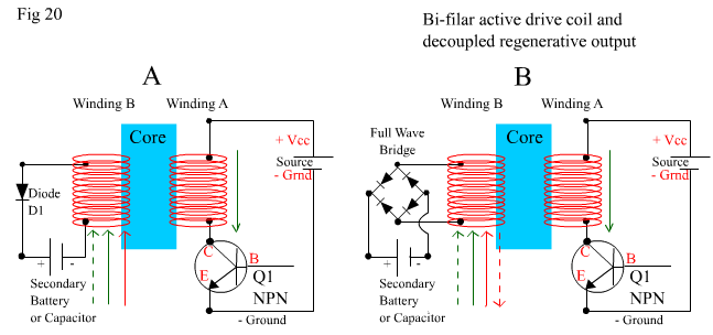
In Fig 20 above Groups A and B are two identical bi-filar wound coils. Group A has winding A connected to the pulsed supply and winding B connected via a Diode D1 to an external Battery (or Capacitor). Group B has winding A connected to the pulsed supply and winding B connected via a Full Wave Bridge to an external Battery (or Capacitor) In Fig 19 on the previous page, the example and description only took into account, the actions and reactions of the core to the supply pulse. Because diode D1 and transistor Q1 were blocking to any reverse currents in their respective coil windings, then we neglected to examine any influence that the high speed changing magnetic field had in creating its own induced AC or Varying DC current into the coils. I tried to keep the explanation within the bounds of supply current only to KISS. (LOL) In Fig 20 above, the secondary winding B in both groups, is electrically de-coupled from the supply of winding A, and is connected to its own load Battery or Capacitor. Each winding B is also de-coupled from its load by either a diode or a full wave bridge. They cannot receive current back from their load. Group A will always take advantage of the pulsed supply, but it will only be influenced by the rotating magnets, when the current induced by the rotating magnets is in the same direction as that shown by the red arrow below winding B. This is because diode D1 only allows current through winding B in one direction. But Group B has a definite advantage as a generating coil because it will receive current from both directions induced by the magnets, shown by the red arrows below winding B, due to the full wave bridge, which allows this. Once again however, "There is no punch without Judy", and in both circuits there will be losses. The regenerative energy is no longer available to the rotor as torque, or the supply as charge, but will instead be off-loaded out of the system. There may be a slight increase in supply current demand in both cases. And the generating capability advantage of Group B, can be quickly offset by supply demand, if too much load current is used from winding B. Also in both cases, the battery being charged has its own internal resistance (so does the supply) and therefore a small amount of the charging energy will always be lost within the battery itself. In Fig 19 on page 6, we were feeding a small amount of energy back to the system as torque, and a small amount as charge. In Fig 20 we are translating all that energy out of the system into another storage area for later use. In both instances we are not making more energy than we put in, we are just using different methods to use the total input energy as efficiently as possible by recycling some of it. And succeeding! Personally if I were using bi-filars for a drive coil, I would be hooking it up as in Fig 19 on page 6, then using the extra torque to power stand alone pick-up coils. Before moving on to examining pick-up coils (where the real lesson is), lets look at other examples as shown in Fig 21 below. |
|
|
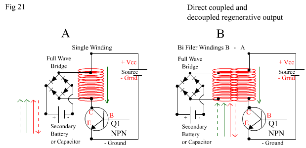
In Fig 21 above, diagram A shows a directly coupled full wave bridge across a single wound active drive coil. Diagram B shows a full wave bridge across winding B which is de-coupled from winding A, which is the active drive coil connected to the supply. Besides electrical isolation in the circuits, what's the difference? Is one more efficient than the other? Coil A has no transference loss between two coils when utilizing the BEMF and CEMF of the leading and trailing edges of the pulses. In Coil setup A, there is a direct loop of all arising current from the pulse within the load and coil, while in Coil B, the load loop and supply loop are isolated but mutually reacting through the inductive core they share. Both Coil A and Coil B will charge a Secondary Battery, but when utilizing BEMF and CEMF there will be less loss in Coil A due to direct coupling. Both coils will experience the same Induced EMF fromthe magnets. Both circuits will suffer from supply current increase if the load is too great. E.G a really flat battery or a capacitor with zero charge in it. Please note also that Coil B doesn't have to be-filar. It can be wound like a traditonal transformer, with a secondary coil wound first over the core, then a primary coil wound over the top. In this way you can step the output up for higher voltage, or down for greater currents. Read some basic transformer theory and apply it to your motors. Play around with the following parameters and you'll have fun. High Current, Low Voltage, High Voltage (be careful), Low Current. If ever there was a way to learn about what works and what doesn't in induction systems, an open system pulsed motor will surely be it! Fig 22 below shows a single active drive coil with either a full wave or half wave rectification. See below for explanation. |
|
|
|
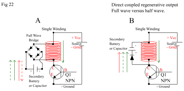
In Fig 22 A above a single coil with a full wave bridge can be seen as influenced by four possible current direction sources. Two from the supply in the form of BEMF and CEMF due to the pulse, and two from the magnets. Fig 22 B shows a single coil with diode can be seen as influenced by three possible current direction sources. Now you might think that four is better than three, but you'll notice in this instance (and in fig 20(B) and fig 21 (A+B)) that the dashed red line in circuit A which represents one half cycle of the Induced Emf from the magnets is shown in opposite direction to all the rest. Thats because it arises at the same time as the "on" pulse, but it is in the opposite direction and is thus an oppositional vector not a complimentary one. If it is too great , it will negate some of the gains already made by the other three vectors and thus be counterproductive. Across a wider range of load and duty cycle, circuit B will be more efficient than circuit A due to the fact that all induced flowing currents are complimentary and unidirectional with the supply current. Proving that KISS is the best in the end! In summary, for absolute maximum torque with minimum supply current draw, over a wide range of duty cycles, use a bi-filar coil connected as shown in Fig 19 on page 6. For maximum charging of a secondary battery with minimum torque loss and minimum supply current draw, use circuit B as shown in Fig 22 above. For anything else use your imagination! and let your understanding unfold! Also remember that the efficient operation of the above circuits is affected by duty cycle, and dwell angle and thus "Timing Factor", which will be discussed later in Optical-Switching. Now I keep referring to "Timing Factor" but really thats just because the terminolgy fits in with the way I have been discussing matters here. Simply – I hope! What I really should be referring to though is "Time Constants". The following links are a must read in order for you to get a good understanding of "Time Constants" and how they will relate to your experiments with different impedance coils.
1. Particular reference to "heel end slugs" in relays.
2. Discussing time constants On the next page we will discuss passive pick-up generator coils, heel end slugs, and that "anomoly" I keep talking about. That "anomoly" is the very thing that makes these motors so controversial! But it may not be what you expect ! |