Page 2 : Simple Circuits – Continued
|
First I need to explain some things about Back EMP (BEMP) and Back Emf (BEMF). BEMP is Back Electromotive Potential while BEMF is Back Electromotive Force. What's the difference? Force is a measure of mass x acceleration. This implies that a movement of mass is an integral part of Force. In an electric circuit, this movement of mass is "current". Whilst there is a lot of debate about whether electrons actually move, or whether their electron "charge" is the only movement in the form of charge energy transfer from atom to atom, the notion of movement is still paramount to the formula of calculating force. For simplicity sake, we will assume that there is movement of some sort and leave it at that. So when we talk about BEMF, it is implied that there is a movement of charge which arises in opposition to the Forward EMF (FEMF supply current). BEMP is Back Electromotive Potential. In order for any BEMF to occur, there must be a BEMP, but the reverse is not always true. I will discuss Collapsing EMP (CEMP) and Collapsing EMF (CEMF) later on in following pages.
|
|
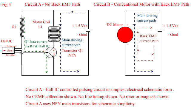
On page 1- I wrote : – "On top of that, normally, the fast rotating magnets that sweep past the coil, also induce an ElectroMotive Force back into the coil which is in the opposite direction to the incoming supply current. This opposing direction of EMF is what is known as Back EMF and happens in all conventional motors regardless of motor type. In the circuits shown above however, this BEMF has no extra ability to reduce the incoming current, but I will explain much further down the track why this is so." In Fig 3 below I have shown a Circuit from the previous page (Circuit A below), and next to it Circuit B which is representative of a conventional DC motor. See below Fig 3 for an explanation of the differences in the current pathways shown. |
|
|
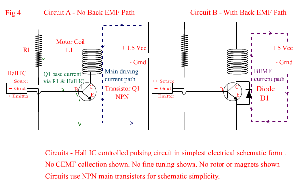
In Fig 3 Circuit B above, a normal DC motor is connected to a supply and promptly increases its speed until it reaches top speed. As it does so, a BEMP arises which produces a BEMF. The BEMF is just like the Forward EMF (FEMF), in that there is a complete loop in the circuit for it to flow. It is never as strong as the FEMF and so the net current flow measured will always be in the direction of the supply current. But in Fig 3 Circuit A above, a BEMP arises, but does not result in a BEMF, because the Transistor Q1 which is forward biased to the supply current, is reversed biased to the BEMF thus effectively blocking any potential current flow in the reverse direction. Because of this, only the increasing impedance of the coil due to pulse frequency is responsible for lowering the supply current through the coil. Now lets move on to Fig 4 below which shows how to incorporate the BEMF into the circuit to lower the supply current even further. See below Fig 4 for circuit differences and explanation.
|
|
|
In fig 4 above, both circuits are identical except for the addition of Diode D1 across the Collector to Emitter junction in Circuit B. This diode now provides a circuit path for the BEMF, and can effectively help to lower the supply current a little bit more. In high impedance coil motors you may not notice a significant change because current draw will already be quite low, but in motors designed to produce a lot of torque by using low impedance coils, the added diode can signifantly contribute to lowering the supply current in conjunction with the coil impedence. Now it also must be said, that the addition of Diode D1 will also effect to some degree the amplitude of voltage "spikes" occuring in the system which are due to the Collapsing EMP of the coil from the pulsing it receives. Normally this is a good thing, because these spikes are generally considered to be bad news, and in conventional systems, they are usually "bled out " of the system in one way or another. If however, these spikes are what you want because of the nature of the experiments you are performing, then simply leave the diode out. Now if you are basing your circuit on the very simple ones shown thus far, and you are not getting high voltage spikes (and you want to), it is likely, that the control circuit needs a bit of fine tuning, to ensure that when the Hall IC is in the "off" mode, your transistor is completely turned "off" and not just switching between states of "slightly on" and "completely on". In Fig 5 below some basic methods of transistor bias control are shown. See below Fig 5 for the circuit explanations. |
|
|
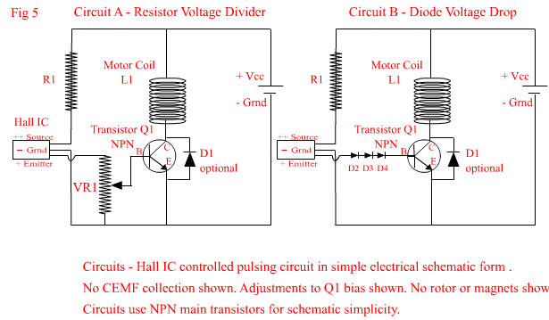
In Fig 5 Circuit A above, a variable resistor has been placed between the switched output of the Hall IC and base of Transistor Q1. This allows some degree of flexibilty in "tuning" the voltage that is applied to the base of Q1. The VR1 (linear Pot – lets say 1000 ohms) as shown, acts as a voltage divider, and the value of the voltage that feeds the base of the transistor is proportional to the position of the the wipe contact in relation to the resistive track of the VR1. If the voltage from the Hall IC output to the top of the VR is 1Volt and the wiper contact is exactly halfway, then the voltage fed to the base of Q1 would be .5 V and Q1 would not turn on. If the wiper is moved towards the top of VR1 the voltage will increase towards 1 Volt and Q1 will turn on when it reaches above .6 Volts(for silicon Transistors). This method offers some flexibility but has the disadvantage that some control circuit current will be shunted to Ground via VR1 and some current will be lost to Q1 even if the VR1 wiper is as the top of the VR1 resistive track. If the current loss is too high due to the value of VR1, then Q1 may still not turn on when required, even when the voltage available is high enough, because transistors are current driven and require a minimum amount of current to "turn on". However, this method should suffice for most experimental purposes, and is very simple to implement. I will address the current loss problem associated with the VR1 in Fig 6. In Fig 5 Circuit B above, small Signal Diodes are placed in series with the output of the Hall IC. Each diode causes a voltage drop of either .6 Volts for Silicon Diodes or .4 Volts for Germanium Diodes. A combination of both types may be used to achieve the desired voltage range required. The actual number of Diodes used will be dependant on the amount of Voltage dropping that is needed to make Q1 turn off completely when the Hall IC is in "off" mode. The advantage of this method, is that no current is shunted to ground, and there is minimal current loss through the diodes when the voltage rises above their total threshold conducting voltage when the Hall IC is switched to the "on" state. The disadvantage with this method is that it lacks runtime flexibility, and if the motor has been running for some time and the supply voltage begins to drop, there will be a point at which the forward bias voltage is no longer sufficient to turn Q1 on. In Fig 6 below, the advantages of both circuits are incorporated together to offer greater flexibility and increased stability, while an extra transistor is inserted (Fig 6 Circuit B) to address current loss problems associated with VR1. See Below Fig 6 for an explanation of the circuit modifications. |
|
|
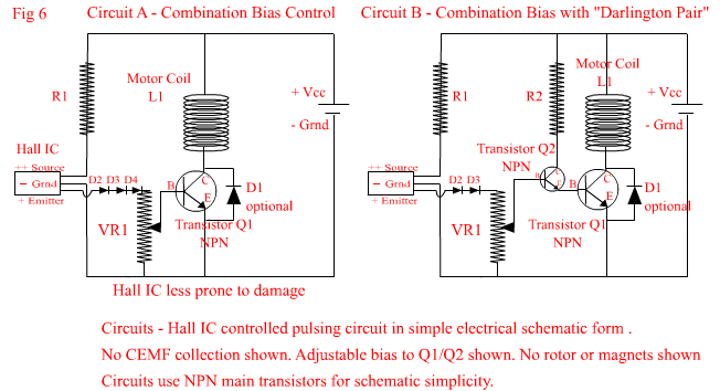
In Fig 6 Circuit A above, the previous circuits in Fig 5 have been combined to produced a more stable circuit which offers a degree of flexibiliy in controlling the amount of bias to Transistor Q1. However, depending on the type and characteristics of Q1, the voltage supplied to the base may be sufficient, but the available Base to Emitter junction current may now be too small to operate Q1 efficiently. In Fig 6 Circuit B, an extra smaller NPN transistor (Q2) has been added to the circuit to form a configuration known as a "Darlington Pair". Because the added Transistor Q2 will add a .6 Volt drop to the base current circuit, one of the signal Diodes has been removed, so that the effective voltage dropping due to "silicon junctions" is effectively the same in both circuits. The advantage of adding Q2 however, is that when it turns "on" due to sufficient bias voltage, it allows extra current to flow to the base of Q1 via R2 and the Collector to Emitter junction of Q2. The amount of extra current available to the base of Q1 will be mostly determined by the value of R2. Circuit B now offers a stable and variable controlling circuit which protects all the controlling components, whilst allowing a greater "turn on current" to Q1, which in turn allows a greater current availability to the motor coil via the Q1 Collector to Emitter junction. If your experimental motor circuit is hooked up in the any of the above configurations, but you are not getting the results you expected, e.g. the rotor is running slower, fairly high constant current consumption regardless of rotor speed, etc, you may require higher resistor values (R1) or more signal diodes, to ensure that your transistor is actually turning off completely. One simple test you can do to see if your transistor (or Mosfet) is turning off properly, is to:
1… Connect your circuit. |
|
In the above circuits I have concentrated on describing the fundamental operation of the circuits and have mostly omitted any actual component values. This is because the values of VR1 and R1/ R2 or the number of Signal Diodes used, are really dependant on the type and characterics of the Hall IC and Transistor/s Q1 and Q2 used. In following page, I will discuss Collapsing EMP/EMF, and how to tap it for charging Capacitors or another Battery or increasing the motor torque. I will also discuss Voltage Regulators and "Mosfets" and the advantages they offer for switching, and will introduce a more practical and more stable controlling circuit. |