|
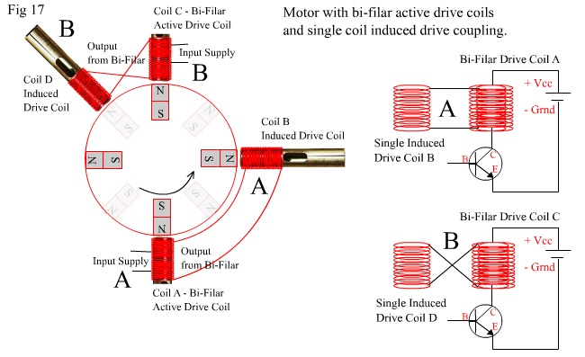
To bi or not to bi, that is the question Horatio! Bi-Filar that is. Do you wind single or double (bi-filar) coils for your motor. Its six of one or a half a dozen of the other! Once again, it depends on your requirement. But I'll assume that you want to wind bi-filar, because you've read all sorts of things about them. We'll throw in a few single wound coils just for the sake of it. After all, we need to compare things to ascertain whether an advantage or disadvantage has occurred. Before we go too far, lets talk about Duty Cycle. What is it? How does it affect the motor running.? Percentage Duty Cycle is a term used to describe the amount of time something is "turned" on compared to the time it is "turned off" before being "turned on" again. So if a rotary machine receives a burst of power at Point A for 1 second and takes another 3 seconds before it gets back to point A (or another burst point B) where it is ready to be given another burst of power, then 1 second out of a total of 4 seconds (1 on plus 3 off) , is 25% of the time of the total cycle. Thus, it will be referred to as a 25% Duty Cycle machine. If it was on for 2 seconds out of the 4 seconds, it would be 50% and if it was on for all 4 seconds it would be 100%. In a machine that uses magnets to trigger Hall IC's, the on time will usually be be the width of the triggering magnets (roughly) and the off time will be the space between triggering magnets (roughly). The On Time + Off time = Total Cycle Time and the % Duty Cycle is the On Time / Total Cycle Time. A conventional shunt wound DC motor is on all the time when connected, thus it's Duty cycle is 100%. See Fig 17 and below Fig 17 for an explanation of the diagram and how Duty Cycle can affects the circuits shown |
|
|
|
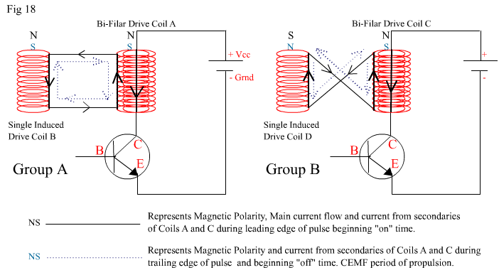
In Fig 17 above there are two active Drive coils which are bi-filar wound, which means two identical lengths of wire have been wound into a coil at exactly the same time together. In this way each coil has exactly the same influence on the core or is influenced by the core in the same way. It is a different method to winding one coil first and then winding the other one over the first, which is very common in ordinary tranformers and inductors. A Bi-Filar coil shares the same induction capabilities as other winding methods including the ability to act as a transformer. In many instances it is the preferred way to make windings. And like a transformer there can be more than just two windings. Tri-Filar and Quad-Filar etc…… The two active drive coils have one set each of their bi-filar windings connected to a single wire induced drive coil. They are divided into Groups A and B. The two groups are wired differently and are spaced differently with respect to the distances between the active drive coil and its associated induced coil. The Drives Coils A and C are active drive coils, meaning that they are connected to the pulsed supply. The drive coils B and D are both "reactive" induced drive coils which derive their power from the transformer effect occurring in Coils A and C. Remember that Bi Filar Coils A and C will be pulsing on and off, and by doing so are acting like a transformer with a primary coil connected to a supply (the pulse) and a secondary coil connected to a load, which in this case are the induced drive coils B and D. When the primary winding of Coil A is pulsed on, the other winding sends induced current in the opposite direction out to Coil B which is also opposite a magnet at the same moment of pulse. The current entering into drive coil B is in the same direction as the primary current in coil A and so it induces into the core the same magnetic polarity as coil A. Both coils will be North pole (in the above example) and the rotor will be repelled away by two synchronous electromagnetic cores. When The Pulse in Coil A turns off, the collapsing field reverses the secondary current pulse and coil B will become a South Pole which is now attracting the magnet which was previously repelled by it. If the pulse is less than 50 % duty cycle, then the rotor magnet will still be less than halfway between the first core (active) and the next core (induced). This will cause some loss of the benefit of the initial Pulse when Coil B was a north pole because the magnet on the rotor will be attracted back to it while its trying to continue its journey to the next core. As Coil C is being pulsed "on", the same induction process is occurring between Coil C and Coil D as between Coils A nd B. But the connections of the output from Coil C have been twisted 180 degrees and the position of Coil D has changed to a place corresponding to the midway point of the pulse cycle. Now when Coil C is pulsed on, it becomes a North Pole repelling the rotor (magnet), and at the same time Coil D becomes a South Pole attracting the rotor (magnet). When the pulse in Coil C turns off, the collapsing field reverses the secondary current pulse and coil D will become a North Pole which is now repelling the magnet which was previously attracted by it. In this instance, if the pulse is less than 50 % duty cycle, then the rotor magnet will still not have passed Coil D before Coil D becomes repelling. This will cause some loss of the benefit of the initial Pulse when Coil D was a South pole because the magnet on the rotor will be repelled back while its trying to continue its journey to and past Coil D. In the example above, if the pulse is exactly 50 % Duty Cycle, then Group A and B will both act in perfect unison and each set of cores will contribute to the overall positive torque of the motor. Group A will provide more additional torque than Group B on the leading edge (turn on) of the pulse while Group B will produce more torque on the trailing edge (turn off) of the pulse. This is due to the relative distance of all cores from the nearest magnet at each edge of the pulse. Both configurations will yield the same net amount of torque. Note that the placement of the induced drive coils above shows the best possible position for 50% duty cycle only. As soon as you change the Duty Cycle to something like 20-25 % then the current phase within the coils will change with respect to the magnet position and firing positions, and this will effect the location at which the coils will give their "maximum perceived benefit", and also the amplitude of that "maximum perceived benefit". Incorrect placement for a given duty cycle will have a negative impact on torque and current consumption. In all pulse motors, 50% duty cycle per phase is the maximum beneficial, usuable, active percentage. Applying power for more than 50 % of the time causes severe loss of torque through to complete motor stall, high current consumption, excessive heating and unnecessary energy waste. It is also rare in most multi-phase pulse motors to run on Duty Cycles of more than 30% per phase as it is not necessary. Correct use of "Timing Factor" can extend the "Virtual Duty Cycle" of each phase in a positive way by recirculation of CEMF, but only below Duty Cycles of 50% and preferably in the region of 20-25 %. This is one of the core benefits of pulsed motors. We will discuss "Timing Factor" and "Virtual Duty Cycle" on a following page, especially as it relates to the collection of CEMF in the drive coil and translation to torque or regenerative charging. Fig 18 below shows more clearly the phase relationship between the active and induced drive coils of Groups A and B from Fig 17 above. |
|
|
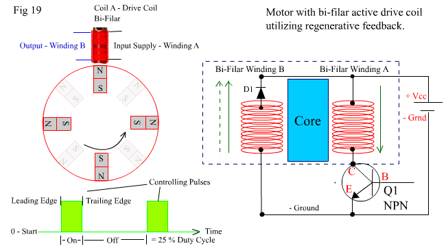
Now after all this, a question begging to be asked is; what advantages, if any, do either of the above two coil configurations have over just using two single wound drive coils A and C only. Why bother with bi-filar coils and the induced coils B and D. The answer is; for not much really!. Especially if you are using solid iron cores! Technically both configurations do increase torque marginally without increasing drive current consumption much, if at all. The small advantage they offer, is that they directly translate the CEMF which arises in Coils A and C into the rotor as added torque. The downside to this arrangement is simple. The extra cores introduce extra magnetic drag. Remember that nasty price you have to pay from drag. Theres always a price, so it isn't all win. The added torque is greater (when using low impedance coils) than the magnetic drag that is introduced, so there is still a small net gain in medium to high power motors. Not Overunity, just a gain in overall efficiency. Bi-Filars can be used in a simpler even more efficient arrangement, which introduces no extra drag at all yet adds to available torque and reduces consumption by translating the BEMF and CEMF of the windings. See Fig 19 below and after Fig 19 for the explanation. |
|
|
|
In Fig 19 above, a single Bi-Filar wound coil is shown. One side of Winding A is connected directly to the positive of the supply while the other side is connected to ground via the Collector to Emitter junction of the controlling transistor Q1. Winding B has one side connected back to the positive of the supply via a diode (D1). The diode prevents it from receiving any input power directly from the supply and provides a return path for regenerative energy. The other side of winding B is connected to the negative (ground) of the supply. |
|
|
|
When the transistor turns on due to a pulse, the bi-filar coil acts briefly like a transformer. During the leading edge of the pulse, the current in winding A shown by the green arrow to the right of winding A, induces a BEMF into winding B. This BEMF normally arises within winding A, but is blocked by transistor Q1. However, the diode D1 is forward biased to the BEMF in winding B, and so current is allowed to pass in the direction as shown by the solid green arrow on the left of winding B. This BEMF current forms a loop * (see note at end of page) between winding B and winding A whilst transistor Q1 is turned on, and has the effect of maintaining a higher supply voltage to winding A by contributing recycled current (BEMF) in conjunction with the supply current to winding A. This in turn, translates to a slightly higher torque, with less total supply current required. Once the leading edge of the pulse passes, this transformer recycling effect disappears until the trailing edge of the pulse occurs. When the pulse collapses (the trailing edge), a CEMF is produced in the same direction as the preceding BEMF and it also is recycled. But its energy goes directly back into the supply as charge, because when Transistor Q1 turns off, there is no path through winding A for current to flow in a circulating loop. The CEMF direction is shown by the dashed green arrow to the left of winding B. |
|
|
|
This coil arrangement is very simple and has a positive impact on total efficiency over a wide range of duty cycles. When using low impedance coils with a short "Timing Factor", duty cycles can go as high as 45 % before the dynamics change from a positive impact to a negative one. As mentioned previously, I'll discuss the term "Timing Factor" in more detail later. Next we'll look at a few more simple methods of capturing CEMF as regenerative energy. ——————————————————————————————————————————– *Note from above* – "This BEMF current forms a loop between winding B and winding A" . This is a neat little trick! Especially when the statement is followed by "This in turn, translates to a slightly higher torque, with less total supply current required. " Lets examine these statements more closely. In a conventional DC motor as outlined already on page 2 with the following statement "In Fig 3 Circuit B above, a normal DC motor is connected to a supply and promptly increases its speed until it reaches top speed. As it does so, a BEMP arises which produces a BEMF. The BEMF is just like the Forward EMF (FEMF), in that there is a complete loop in the circuit for it to flow. It is never as strong as the FEMF and so the net current flow measured will always be in the direction of the supply current." When the BEMF arises in the DC motor to its maximum, then current draw will be at its minimum, due to the opposing EMF's, RPM will be at a maximum, and actual torque will be at a minimum! Don't take my word for it. Check out the torque characteristics of any Permanent Magnet DC motor. Their maximum torque is at Zero Rpm. (maximum Current draw!) Have you noticed that when you hook up a high speed Permanent Magnet DC motor without a load for just 5 minutes, they still get quite warm to hot. After thirty minutes of continuous running they are definitely hot. Think about the Forward and Back EMF fighting it out against each other in the coil wire. Forward Current wins after battling its way against this BEMF the whole time. So where do you think most of the heat is coming from! Is it just from driving current. No, not when the motor is free wheeling with zero load. Thats when the "apparent" supply current is at its lowest! Yet still they run hot. It's because two big opposing currents are playing "push the other guy", and only one is winning by a small amount!. The "apparent" low current we measure. The statement "This BEMF current forms a loop between winding B and winding A" reveals a wonderful trick of the circuit in Fig 19, whereby, an induced current which normally opposes the inducing current, is re directed to assist the current it normally opposes. In doing so it acts cohesively and unidirectionally, with the inducing current. A quick re-glance at Fig 19 above, shows both the supply current through winding A, and the CEMF from winding B (when followed around the circuit) wind up in the same direction through winding A. The currents are not fighting each other, they are mutually co-operating with each other! Result – more torque, less supply current! less heat! |