Page 3 : Simple Circuits – Continued
|
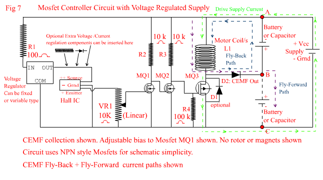
On this page, we finally get to collecting CEMF from the drive coil. Fig 7 below introduces a more sophisicated controlling circuit utilizing a Voltage Regulator and Mosfets to do the switching. The circuit also introduces a CEMF output and two different paths in which it can be connected. One path is often referred to as "Fly-Back" and the other path can better be described as "Fly-Forward". Fly-Back is essentially a method of recapturing some of the energy stored in the drive coil when the drive coil circuit is turned off. Generally speaking, if the Fly-Back circuit is connected to another Battery , the motor will continue running without any loss of Torque or running speed, but it will only charge the secondary Battery at a smaller charging rate than the discharging rate of the supply Battery. The most Current you will be able to recover is around 25-30 % of the drive Current. However this is a true recovery path and will not cause the drive circuit to consume more Current than it would if you didn't connect it. If you use this Fly-Back path to charge an Electrolytic Capacitor which has zero charge in it, then initially the motor will slow down and consume more Current until the Voltage in the capacitor climbs to the same level as the forward Voltage measured across the coil. Actually this is also true of a secondary Battery if the Battery is really very flat and its Voltage is significantly lower than that of the supply Battery. Once the Voltage in either the Battery or Capacitor reaches the same Voltage as the forward coil Voltage, there will be no more negative impact on the drive circuit and you will be recovering Current at no drive expense. Many people think that if a really high Voltage spike is produced by their circuit, then surely they must be able to recover more Current than they put in. The answer is no. If they were measuring really high Current spikes then they would really be onto something fantastic!!!; and I would really love to know about it !!! But collapsing magnetic fields which produce CEMP do not produce high Current spikes, they only produces high Voltage spikes. These high Voltage spikes generally have a greater negative impact on Batteries and circuit components than any positive usefulness. Fly-Forward is simply a different way of directing the CEMF through the circuit. It acts like a current pump because it adds the CEMF to the supply battery EMF in series with each other and can be used to charge a secondary Battery (or Capacitor) at a much higher rate than Fly-Back. But it will severely inhibit motor running speed and torque, and the Current drawn from the supply will increase dramatically. In essence Fly-Forward is a method of stepping up DC to a higher DC value without the use of Transformers and the need to convert DC to AC before stepping up through a transformer can occur. When connecting the circuit to utilize Fly-Forward, the coil doesn't actually experience a time when there is no Current flowing through it, (unless the operational duty cycle(on time) is very low) even when the drive Transistor or Mosfet is turned off. Instead the coil experiences a state of "low Current" when the drive circuit is "on" and a state of "high Current" when the drive circuit is "off". In both Fly-Back and Fly-Forward cases, no extra free energy is obtained. Utilizing Fly-Back can be considered as a method of lowering the overall power consumption of the motor because it re-collects stored energy from the coils between pulses, and dumps it into a secondary Battery for later re-use. With the aid of bi-filar windings on the drive coil, it can also dump the stored energy directly back into the supply battery in between forward Current pulses. I will discuss various coil designs in following pages. Note that if a Battery is connected to the Fly-Forward path, there is no longer any CEMF available for the Fly-Back path. In other words, you can't collect Current from both paths at the same time. See below Fig 7 for an explanation of the Mosfet circuit operation and the Fly-Back and Fly-Forward paths. |
|
|
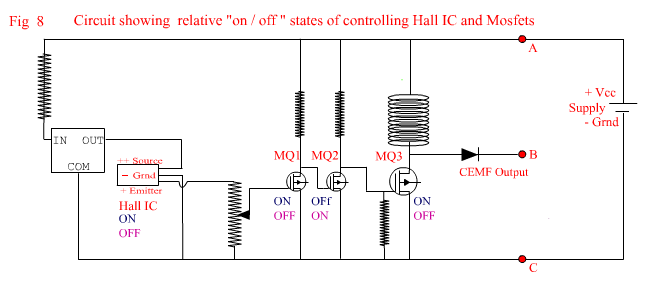
In Fig 7 above, the Hall IC supply circuit is fed via a Voltage regulator that can be a fixed output voltage type or a variable output voltage depending on the type of regulator used. If using a fixed output type, it still may be necessary to incorporate a resistor or diodes in series with the Hall IC supply to achieve the desired voltage range necessary (in conjunction with VR1) to turn the Mosfet MQ1 on and off. In this circuit there are three Mosfets which are hooked up in a "flip flop" arrangement to turn the drive circuit on or off. Why go to all this trouble of adding extra components? Well Mosfets are Voltage controlled not Current controlled, though they do still require a small amount of current to turn on. Like Transistors they will turn on at at .6 Volts but if the Gate to Sink junction (equivalent to base-emitter junction of a transistor) is fed a voltage of 10Volts or more, then the Source to Sink junction (equivalent to collector-emitter junction of a transistor) will have a resistive value of .001 or less ohms, which is very nearly zero resistance. This makes Mosfets ideal for pulse generating and DC motor control circuits, and indeed, is generally what they are used for. If Mosfets are fed 10Volts or more to the Gate (base), they will have almost nil voltage drop across the Source to Sink junction, and very little heat will be created within the Mosfet, and hence miniscule heat losses are incurred. Because the Gate to Sink junction current requirement is in the high micro-amp range (below milli-amp range), then a few extra components will only introduce micro-amp Current losses. Now lets look at how the circuit achieves the switching and provides a higher Voltage to the Gate of the drive Mosfet MQ3. When the Hall IC is "on", MQ1 will also be on, but MQ2 gets its Gate Voltage from the Source connection of MQ1 via R2 which is 10,000 ohms. This voltage will be no greater than .6V because MQ1 Source to Sink Junction is on. The current available to the Gate of MQ2 is now only 60 micro-amps, so effectively, MQ2 remains off. The drive Mosfet MQ3 Gate, likewise gets its Voltage from the Source connection of MQ2 via R3. Since MQ2 is off, then the Source to Sink junction of MQ2 is effectively open circuit, and the Voltage at the Source of MQ2 which is connected to the Gate of MQ3 is nearly the full Voltage of the Supply, but the current is limited by R3 which is also 10,000 ohms. If the MQ3 Gate voltage is 10V, then the current will be 10V divided by 10,000 ohms(R3), which is 1 milli-amp or 1000 micro-amps, which is enough to ensure MQ3 turns on. When the Hall IC turns "off", MQ1 turns off, which raises the Voltage to the MQ2 Gate to nearly the full Voltage of the Supply and MQ2 turns on. When MQ2 turns on, the Voltage to the Gate of MQ3 drops to .6V with a current of 60 micro-amps, and thus turns off. Because the turn on/off time of Mosfets is so quick, the pulses generated are very sharp and clean. Note that there is a 100,000 ohm resistor (R4) between the Gate of MQ3 and ground. Because Mosfets have a very high Gate to Sink impedance, they can be destabilised and affected by sudden and high voltage variations in the Source toSink (driving) circuit feeding back into the supply as high voltage spikes.. Resistor R4 absorbs any such fluctuations and keeps the pulse produced by MQ3 clean and sharp, without bleeding away too much current because of it's high resistance value. You will notice in Fig 7 that I have included Diode D1 in the circuit as optional, but some Mosfets have a Sink to Source reverse biased diode already built into them, which takes away the option of not including it in the circuit. See Fig 8 below for a pictorial representation of the various "ON/OFF" states of the Hall IC and the Mosfets.
In Fig 7 above, there are 3 points on the circuit labeled A,B and C. If you connect a Battery or Capacitor across points A and B. then you are utilizing Fly-Back. If you connect a Battery or Capacitor across points B and C then you are utilizing Fly-Forward. Make sure that whichever points you connect to, you place the Battery or Capacitor in the right polarity direction as shown in the circuit. If you don't connect the polarity correctly, you will experience BIG problems!! Also you will notice the addition of Diode D2. This Diode (D2) is essential for the collection of CEMF, and also to prevent short circuits occurring when adding a secondary battery to the CEMF output. Without a diode, the secondary battery will be permanently connected across the coil if used in the Fly-Back arrangement, and will short circuit itself when the Mosfet MQ3 is turned on if it is connected in the Fly-Forward arrangement. You may notice also, that whether you are using the Fly-Back or Fly-Forward paths, the current through the coil is always in the same direction as the main supply current The circuit in Fig 7 is very stable and very useful, but while VR1 offers some flexibilty in controlling the duty cycle ("on" time), said control is still largely limited and determined by the width of the triggering magnets ("on") versus the width of space between them ("off"). Once again I have only given specific values for some components. Namely the resistors. If you are an experimenter such as myself, then you are likely to be cutting costs by cannibalising old circuit boards. The circuit I have shown with resistor values given, will work with a large variety of Mosfets with different characteristics without causing component failure. As before, use this circuit as a guideline rather than a gospel. Also note that any of the previous simpler switching circuits on page 1 + 2 have the same capability of supplying CEMF by the addition of the diode (shown as D2 in the diagrams on this page) on the appropriate side of the coil and providing a Secondary Battery or Capacitor to charge in Flyback or Flyforward mode: Note:* Flyback recommended . |