The Mini-Romag generator from Magnetic Energy is composed of two main parts : The Rotor and the Stator.
– The Rotor is a brass cylinder with 6 pairs of magnets placed at 60° around its circumference. The magnets polarities are alternatively North and South.
– The Stator is a copper cylinder with 6 flat coils wounded so as the coils axis are tangent to the rotation of the rotor. So, only the orthogonal component of the magnetic field of the magnets is used.
The oscilloscope pictures below, show the signal generated by a moving magnet :
– The left picture is the voltage generated across the coil when a magnet axis crosses the coil axis, this is a conventional setup for a magnetic generator.
– The right picture is the voltage generated across the coil when a magnet axis crosses the middle of the tangent coil (orthogonal component of the magnetic field), this is the case of the Mini-Romag generator.
-
In the left case (conventional generator), you can notice that the signal induced across the coil is symetrical Vs the zero line, the voltage value induced during the approach phase is equal to the voltage induced during the exit phase. During the approach phase of the North pole of the magnet (from the left to the coil axis), a North pole is created on the bottom surface of the coil (according to the Lenz law), this creates the negative voltage shown. When the North pole of the magnet leaves the axis of the coil, a South pole is created on the bottom surface of the coil (according to the Lenz law), this creates the positive voltage shown in the scope picture. The flux in the coil has been reversed in this case. In this case there is always a magnetic coupling between the rotor (magnets) and the stator (coil).
-
In the right case (orthogonal field (Mini-Romag Setup)), you may notice that the voltage induced is more positive than negative (asymmetrical) when the magnet crosses the middle of the tangent coil. During the approach phase of the North pole of the magnet (from the left to the middle of the coil), a North pole is created on the left surface of the coil (according to the Lenz law), this creates the negative voltage shown. During the exit phase of the North pole of the magnet (from the middle of the coil to the right), a South pole is created on the right surface of the coil (according to the Lenz law), this creates the negative voltage shown. The coil flux has never been reversed in this case. Now, look at the middle position (when the magnet crosses the middle of the coil). In this case, the orthogonal magnetic flux density drops to zero (this has been checked with a gauss meter). So the positive pulse induced in the coil is not due to the moving magnet, but it is generated by the collapse of the magnetic field (Back EMF)….In this case there is no magnetic coupling between the rotor (magnets) and the stator (coil) during the positive phase of the signal generated.
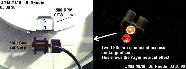
This has been confirmed experimentaly. I have used a simple coil with an air core (no drag effect). A simple diode has been used to short the back EMF part, and you can notice that the rotor speed remains constant….
Another test has been conducted by connecting the coil to a power supply (up to 1.37A), I have noticed no significant change in the rotor speed.
So, I have tried to explain only the half part of the Mini-Romag principle, the non-reciprocal effect when the device acts as a generator.
-
Now, how is the device able to run itself as a motor/generator ?