|
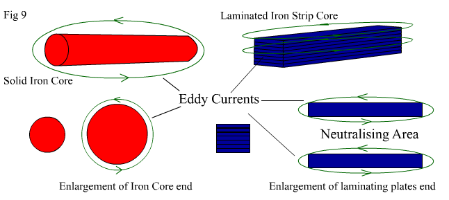
Before continuing with any more circuits, lets examine the coil. After all, without the coil, there is no "motor " in a pulsed coil motor! And "In short", there is also NO "In Short", when it comes to talking about coil design. Especially when we are talking about pulsed motors, and even more importantly when we are talking about open magnetic system pulsed motors. Throw into the mix different requirements, e.g low speed high torque, high speed low torque etc, and the party really gets cranking! Coils! who's got coils? When talking about "Adams" motors it is very important to understand that there is only one significant difference between an "Adams" motor (and for that matter, a "Bedini" motor), and any other so called conventional pulsed motor (and there are plenty! – just how do you think your computer hard drive is spinning?) and that significant difference is the magnetic circuit. In conventional systems, the magnetic "circuit" or "field " is closed. In a sense, it is almost short circuited, with only the air gap between the rotor and stator offering a small degree of magnetic insulation to an otherwise would be closed magnetic system. The logic behind this has always been two fold. One is the assumption that, by bending the flux from the rear of the magnet or coil by way of metallic form work, (the side of the magnet not directly facing the coil and vice verse) to an area where it will be productive, this will increase overall torque. Which it definitely does (usually in well designed systems). But at a price!! (the reasons for which I will elaborate much later on.) The other assumption is that by using a closed magnetic system, the imperfections in the system, such as sparking brushes (which are common in series wound motors used for most work tools), will not create undue RF interference, because the Closed Magnetic System allows the entire motor to be encased in an iron shroud without affecting its performance, and it is effectively encased in a "Faraday Cage". This is also a good thing for this very reason alone. Imagine if every brush driven electric drill, saw, etc, were not effectively shielded to some degree by their inherent design. I know some cheap brands on the market, and they are not sufficiently shielded, but from my inspection of the goods, I dont think they will last long enough to be a persistent RF problem! After many years of experimenting with "Adams" motors, I can say two things for certain. An Open Magnetic System acts and reacts differently to a Closed Magnetic System and "Adams" motors/generators are a challenge to design for a specific purpose, because, by their very nature, they are "Dynamic". Dynamic in the sense, that, by varying just one parameter of an operating motor, all other parameters change in response. As such, their behaviour is not "Linear" but instead conforms to a set of rules drawn from existing electrodynamic laws, but exhibit anomolous results just the same. The Anomolous Behaviour of Open Magnetic Systems is, I believe, an area of ElectroMagnetic Theory which needs some serious investigation, research and rethinking. If you persist long enough with your "Adams" motors, I personally still doubt that you will ever achieve overunity (I'm quite skeptical in fact! – Please prove me wrong!), but you will definitely witness certain phenomena which are not covered in your average Technicians text book. And yes, I will discuss at great length, in another page, an anomoly which can be put to good use. Now lets talk cores and coils! Because thats where all the goodness happens! In Fig 9 below, we have a pictorial representation of two core types. See below Fig 9 for an explanation of the relevance of the two different cores types. |
||||||||||||||||||||||||
|
|
||||||||||||||||||||||||
|
In Fig 9 above, there is a (Red) picture representing a solid soft iron core. There is also an enlarged front end view. Around the pictures are green lines. Next to the solid core is a (Blue) picture representing a core made by stacking or "Laminating" strips of soft flat iron.. The green lines are representative of the fact, that when a magnet is constantly passing in front of the end of the cores, electric currents are set up within the cores themnselves. These currents are called Eddy Currents. They can be running in more than one direction at a time. They can run from one end of the core to the other, and they can run around the circumference of the iron material. According to accepted electrical theory, these Eddy Currents reduce the efficiency of the coil as both a transmitter and recevier of power via directed induction, by interfering with the preferred induction path. I agree. However it is also accepted electrical theory, that these eddy currents can be minimised by using laminated plates. Notice on the lower right of Fig 9 I have shown a blow up of the iron strips (which are all covered in an insulating film) and an area titled "Neutralising Area". Theory says that ordinarily large Eddy Currents which may be produced in solid cores, can be reduced by laminating, because by laminating you break up singular large eddy currents into numerous smaller ones, and also, these then counteract each others influence due to the oppositional fields they produce. Effectively they self cancel as indicated by the arrows facing in opposite directions in the area between the two plates. I also agree. Please Note, that the solid red circular iron core, could be made into a type of laminated core, by substituting a single large core, with muliple smaller diameter cores (e.g soft iron nails), packed into the same area. |
||||||||||||||||||||||||
|
From my agreement to the above two statements regarding eddy currents you might be thinking, AHAH, so I should use laminated cores for my coils then! Well lets just talk a little bit more about coils/cores and what makes one better than the other, depending on requirement. First, what about air cored coils? They have no iron content at all! And do not suffer from eddy current problems!. So maybe I should use those. Well maybe, maybe not. You see, no matter which coil core you use, there will be an upside and a downside. See the Table Below for a quick rundown on the pros and cons of each sort. |
||||||||||||||||||||||||
|
||||||||||||||||||||||||
|
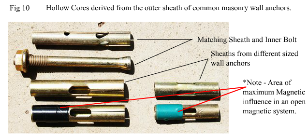
So which coil core do I prefer from the above as the most effecient coil for driving the rotor?, and which do I prefer as a standalone generator coil ? – Answer = NONE OF THE ABOVE ! It's a trick question really because there's one (or more) core/s. I hadn't mentioned. But one in particular. Its a Hollow Iron Core, or much more specifically in a generalised sort of way (LOL!) Its a Hollow Iron Alloy Core. And the best thing is, the perfect piece of metal and core design are already easily available from any Hardware and Building Supplies. They are common and are manufactured by a number of companies all over the world. You're gonna say Huh? when you look at Fig 10 below, so read beneath Fig 10 for a further explanation of these cores, for both energising and generating purposes.
|
||||||||||||||||||||||||
|
||||||||||||||||||||||||
|
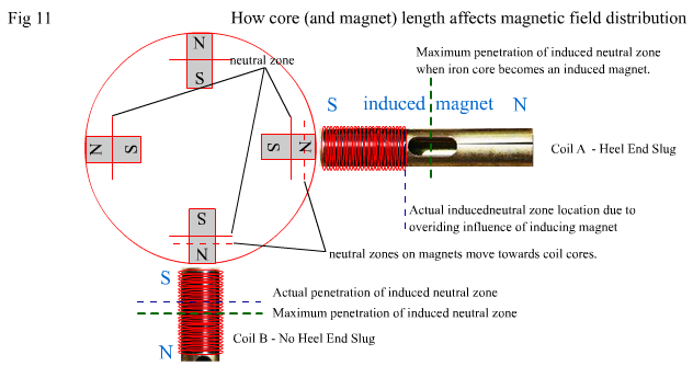
The photo in Fig 10 above is of common masonry anchors which come with an outer sheath which is made of a particularly nice alloy, which, though I actually don't know what its composition is, I know what its composition can do! I tried on numerous occasions to get details of the composition of the alloy, so I could get some specific cores custom made from it, but you'd think I was trying to extract a good tooth from a dentist! Stonewalled for no real known reason. But no matter, I didn't chase it too hard, and if you want to, you can chase up that information yourself. The ones I used were marketed as "Ramset" and I got them from Mitre10 Hardware (Australia). I am sure they are manufactured to an international standard specification as a requirement for general commercial building use. I know they are an alloy of some sort, they are slightly lighter than soft iron, but exhibit high rigidity. I suspect they are made from a mixture of iron, tin and nickel. By the way, you don't need the Nut and Bolt! But it'll come in useful for something else, so don't throw it out! Now what's so special about hollow iron alloy cores and their shape? Well I completely stumbled onto the unique magnetic properties of the alloy and the already-made shape by total accident. Well actually I have to put a bit of "stubbornness" into the picture as well. Either way, it was a case of "necessity is the mother of invention". I had decided during one set of experiments that I wanted to try a hollow iron core, based on the idea, that 90% plus of the induction from the core to the coils happened in the outermost region of the core, because changing magnetic fields would take the path of least resistance and follow the "skin" of the core. Much the same as electrons follow the skin of a conductor in greater numbers than the centre. The only thing I had available to experiment with at the time that even vaguely resembled a hollow core (in my thinking) were wall anchor outer sheaths leftover from home renovating. Thank goodness for the luck of the Irish! Serendipity Rules! I used them initially as generator pickup cores and went WOW, thats Reeeeeally Freaky! I spent the next 10 months investigating every aspect of the cores with their precut shape. This particular core type will be referred to again later on and its unique qualities explained in greater detail. I will also explain in detail the previous "anomoly" I mentioned that can be used to advantage, but I will reserve that for much later down the track. For now I will stick to some conventional theory and concentrate on cores and coils. It's early days yet before we start exploring "anomolies".! Now you will notice that two of the sheaths in Fig 10 above have tape wrapped around a segment of them and it says "Area of maximum Magnetic influence in an open Magnetic system". I have to assume somewhere along the line that you've made your rotor, and you are mounting your coil in front of the rotor. In an open magnetic system, the Neutral Zone of the magnetic interaction will shift from the magnets own center to a point between its own center and the centre of the influenced body. That is, the coil core. See Fig 11 below. The Neutral Zone is where the forces of the magnet's attraction to an external element is equal from each pole and therefore has a net attraction of zero on that element. It usually lies at the centre of the magnet depending on the directional influence of another magnetic/reactive body. |
||||||||||||||||||||||||
|
|
||||||||||||||||||||||||
|
In Fig 11 above, we have two hollow iron alloy cores with identical coils wound on them.. When approached by a magnet they become magnets themselves, and form their own Neutral Zone. This induced Neutral Zone wants to establish itself near the centre of the core, with its own South pole facing the North pole of the magnet, and its own North pole facing away from the magnet . Coil A has a long core and is wound in what is known as Heel End Slug Configuration. Coil B is on the same hollow core material, but it has been cut down to the same length as the coil winding. A standard practice in most cases. What, if any, advantages does Coil A have over Coil B and vice versa? Well that depends on your requirements. If you want to use Coil B for a drive coil, it will be marginally superior, delivering a slightly higher torque availability, due to its lower inductive reactance (because it has less core material). But if you want to use the coil for a generator pickup then Coil A is far superior. This is because the Neutral Zone in the core of Coil A extends out beyond the area of the coil windings, while in Coil B the Neutral Zone maximum extends only to half the coil area.. In both instances the Neutral Zone tries to extend towards the middle of the core as normal.. But because the core in Coil A is long, then more of the coil is exposed to the "same magnetic polarity" of the induced magnetism of the core. The voltage produced by Coil A will be significantly higher than Coil B though the maximum current availability will be almost the same into a given low impedance load. The higher voltage stems from 2 influences. The greater amount of coil windings appearing on the "same side of the induced Neutral Zone" in Coil A, and the greater inductive reactance caused by the extra metal in Coil A which is not present in Coil B. |
||||||||||||||||||||||||
|
|
||||||||||||||||||||||||
|
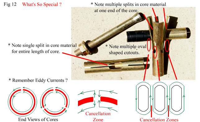
Now what about those core shapes? Whats so special?. Fig 12 below shows the sheaths exposed for analysis. See below Fig 12 for explanation. |
||||||||||||||||||||||||
|
||||||||||||||||||||||||
|
Remember Eddy Currents? The bane of power transformer and inductor designers! An analysis of the pre-formed shapes of these cores, reveals that they have their own built in Eddy Current Suppression. The slotting and cut out areas form "skin paths" for counter running eddy currents to cancel each other out. Neat Hey! Its like using laminates, but without the hassle of bundling the plates together. And if you're winding your coils directly onto the sheaths (with a paper insulation wrapped onto the sheath first), their round shape makes winding easy. In fact the nut and bolt that you shouldn't have thrown away can be used as part of the jig you create to wind your coils! On top of that, the alloy itself has high permeability, low magnetic retention, resists oxidation, and is cheap and easy to source. The hollow alloy core is more efficient than a solid core or laminated core in translating magnetic induction in the core to useful electrical output from the coil. It has the advantage of a solid core, in that it produces a high permeability environment for maximum induction, creates a strong magnetic field not prone to distortion, yet it offers considerably less magnetic drag and a higher electron yield per unit of core mass than a soft iron solid core or laminated core. Summary: The hollow alloy core achieves this superior translation through 3 main causes. 1.) The "skin effect" which concentrates the magnetic flux into a region which is very close to the actual coil windings. 2.) The actual core material has superior magnetic coercian and induction properties to that of soft iron alone. 3.) The core structure minimizes rampant Eddy Currents, thus maximising positive induction potential. This makes it suitable for use with high torque motor designs, and also for generator designs**
Keep On Keepin On! – More to come……. |
simple Adams motor concept 亚当斯电机原理04
佛心
You must be logged in to post a comment.