Page 14 – Dealing with Rotor Induced Counter (Back) EMF – Update/March/2012
Final
|
On the pages 12 and 13, I used Leds in the circuit to give visual indications of current flows. In the following experiments, the Leds are discarded in the CEMF circuit path. Without the 1.8 volt drop across the Leds, more current flows into the battery2. This means there will be a greater load on the flyback circuit (includes motor coils), than in the previous experiments. The purpose of the following experiments, is to explore the motor speed characteristics during higher cemf current loads. In this set of experiments, there is no blocking diode when the transformer/coil configuration is used. Once again, to establish a baseline for the experiment, the first set of figures below shows the motor running with just a blocking diode and no cemf load.
|
|||||||||||||||||||||||||||||||||||||||||||||
|
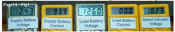
Fig1 Shows only the motor running with a blocking diode in circuit. – Baseline figures – Motor running with no cemf load connected. |
|||||||||||||||||||||||||||||||||||||||||||||
|
|||||||||||||||||||||||||||||||||||||||||||||
|
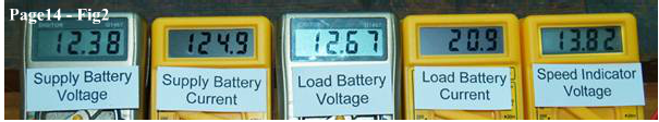
Fig2 Shows motor running with a blocking diode in circuit and direct diode flyback circuit switched on, with battery2 as cemf load.
|
|||||||||||||||||||||||||||||||||||||||||||||
|
|||||||||||||||||||||||||||||||||||||||||||||
|
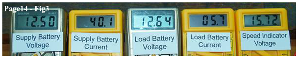
Fig3 Shows motor with no blocking diode, and a transformer in series with motor coils and flyback circuit switched on, with battery2 as cemf load.
|
|||||||||||||||||||||||||||||||||||||||||||||
|
|||||||||||||||||||||||||||||||||||||||||||||
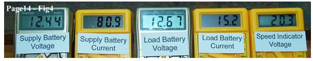
| Fig4 Shows motor with no blocking diode, and a transformer in series with motor coils and flyback circuit in series with voltage indicator coils with battery2 as cemf load. | |||||||||||||||||||||||||||||||||||||||||||||
|
|||||||||||||||||||||||||||||||||||||||||||||
| See Summary Table1 below. | |||||||||||||||||||||||||||||||||||||||||||||
|
|||||||||||||||||||||||||||||||||||||||||||||
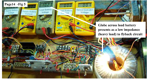
| Results are interesting and encouraging, so the next experiment presents a heavier low impedance load to the flyback circuit. The battery2 in the flyback circuit has been drained to a lower voltage by a 12V 10 watt globe, which is still connected across it's terminals during the test, to maintain a low load battery voltage. The flyback circuit will therefore experience a greater load than in the experiment above. As before the first meter readings shown in Fig6 further below are the baseline readings with only the motor running with no load and a blocking diode is in circuit. Fig5 below shows the test rig with the globe across battery2 terminal nestled into the toroid and keeping battery2 at 10.23 Volts | |||||||||||||||||||||||||||||||||||||||||||||
|
|||||||||||||||||||||||||||||||||||||||||||||
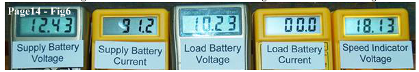
| Fig6 Shows only the motor running with a blocking diode in circuit. – Baseline figures – Motor running with no cemf load connected. | |||||||||||||||||||||||||||||||||||||||||||||
|
|||||||||||||||||||||||||||||||||||||||||||||
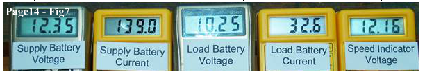
| Fig7 Shows motor running with a blocking diode in circuit and direct diode flyback circuit switched on, with battery2 as cemf load. | |||||||||||||||||||||||||||||||||||||||||||||
|
|||||||||||||||||||||||||||||||||||||||||||||
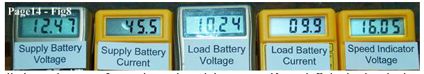
| Fig8 Shows motor with no blocking diode, and a transformer in series with motor coils and flyback circuit switched on, with battery2 as cemf load. | |||||||||||||||||||||||||||||||||||||||||||||
|
|||||||||||||||||||||||||||||||||||||||||||||
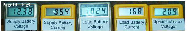
| Fig9 Shows motor with no blocking diode, and a transformer in series with motor coils and flyback circuit in series with voltage indicator coils with battery2 as cemf load. | |||||||||||||||||||||||||||||||||||||||||||||
|
|||||||||||||||||||||||||||||||||||||||||||||
| See Summary Table2 below. | |||||||||||||||||||||||||||||||||||||||||||||
|
|||||||||||||||||||||||||||||||||||||||||||||
|
|
|||||||||||||||||||||||||||||||||||||||||||||
|
As you can see in the previous experiments, the higher flyback circuit load is very counter productive to rotor speed when only using the blocking diode and direct diode flyback output. However it can also be seen that the direct diode output consistently delivers a higher current into the load battery2 than the transformer/flyback coils circuits. The transformer and flyback coil configurations, do however, show a consistent increase in rotor speed (torque) accompanied by lower supply currents, even without the use of a bemf blocking diode. |
|||||||||||||||||||||||||||||||||||||||||||||
|
|
|||||||||||||||||||||||||||||||||||||||||||||
|
|
|||||||||||||||||||||||||||||||||||||||||||||
|
|
|||||||||||||||||||||||||||||||||||||||||||||
|
Just for the record, I haven't shown the transformer circuit performance without a flyback load connected, and I haven't shown direct diode ouput in series with the flyback coils without the transformer interface. So the two Figs below show these. |
|||||||||||||||||||||||||||||||||||||||||||||
|
|
|||||||||||||||||||||||||||||||||||||||||||||
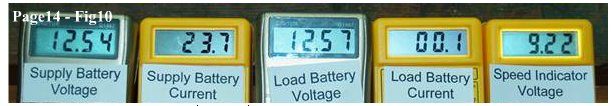
| Fig10 below shows the readings with just the transformer connected in series with the motor with no flyback circuit connected. No Blocking Diode. | |||||||||||||||||||||||||||||||||||||||||||||
|
|||||||||||||||||||||||||||||||||||||||||||||
| As can be seen by the meter readings, the current is low (23.7ma) but the speed is also very low. The transformer/coils arrangement will only produce its highest motor speed when the cemf circuit is connected and heavily loaded. | |||||||||||||||||||||||||||||||||||||||||||||
|
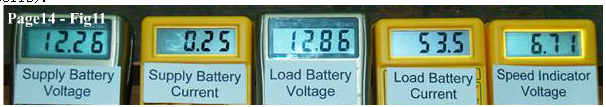
Fig11 below shows the readings with the motor running with just a blocking diode, and the direct diode flyback output is in series with the voltage indicator coils (flyback coils). |
|||||||||||||||||||||||||||||||||||||||||||||
|
|||||||||||||||||||||||||||||||||||||||||||||
| The result is catastrophic. The current consumption is very high (250ma), and the rotor speed is very low, however it can be seen that the maximum load current into battery2 is achieved. In terms of rotor speed versus current consumption, it is clear that directly connecting the cemf diode via the voltage indicator coils (flyback coils) is counter productive and very inefficient. Without the intermediate presence of the transformer, trying to use the relative speed voltage coils as flyback coils results in poor performance. This is true regardless of the polarity of the voltage indicator coil connections to the diode. A different physical relationship (angle) between the drive coils and flyback coils may yield very different results. | |||||||||||||||||||||||||||||||||||||||||||||
|
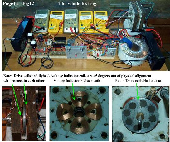
The fact that these experiments have been carried out using air coils is important to me, because they preclude any existence of core drag, and any speed/torque increase being attributed to neutralizing that drag. This leaves the experiments free from those considerations, and able to explore other mechanisms for increased efficiency. Another interesting aspect of the transformer/coils configuration compared to the motor coil only configuration is the relative characteristics of the cemf current into the load battery2 when there is a physical load put onto the rotor. In the instance of using motor coils only, with direct diode output, the cemf current reduces as the rotor speed reduces due to the physical load. The supply current also increases with the application of a physical load. But, while the supply current also increases with the application of a physical load in the instance/s of the transformer/coils configurations, the cemf into the load battery2 does not reduce as rotor speed reduces, but actually increases. Fig 12 below shows the whole rig used for these experiments and the rotor and coils. |
|||||||||||||||||||||||||||||||||||||||||||||
|
|||||||||||||||||||||||||||||||||||||||||||||
| You can see from the photo above, why the poorly made and badly balanced rotor was destined for the junk heap. Thank goodness it never made it there. It still proved itself to be useful for these experiments. Now if I can get such positive torque results with this novel tranformer/coil circuitry using a rotor assembly like the one above in Fig12, then I'm pretty sure a precision made rotor/motor will yield significantly better results. | |||||||||||||||||||||||||||||||||||||||||||||
| The experiments shown on pages 12 to 14 were carried out using cheap and inaccurate Digital Multi-meters. I have in no way attempted to accurately measure power consumed, or torque delivered. I am not claiming OU or anything for that matter. I have just presented the actual test data for your consideration. The experiments are relative experiments only. The same "bad measuring sticks" have been applied to all configurations. LOL. This circuit is new to me, so I have not attempted to give a complete analysis. I do not possess scopes or even quality DM's for that matter, and I believe, that to fully understand the power phase relationships in the transformer/coils circuit, may require the use of some decent scope-ware. Hopefully, this series of experiments has ignited your own curiosity, and perhaps you will diligently set up your own test rigs and circuits to explore what may or may not be an inherently useful pulsed motor circuit. For me these experiments have answered a few questions and raised a few more. | |||||||||||||||||||||||||||||||||||||||||||||
| Cheers and keep on motoring ! |