Page 13 – Dealing with Rotor Induced Counter (Back) EMF – Update/March/2012
Continued
|
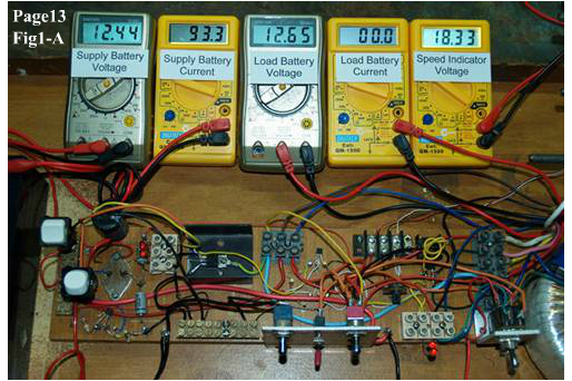
The following experiment is intended to give visual confirmation that the BEMF and CEMF current paths take the routes shown on Page 12- Fig1, and are two separate forces that emerge independently, taking different paths in the circuit. In the photos presented below, one set of Leds (lower left) indicate the back emf path and one set (lower right) indicates the cemf path. In this experiment the bemf blocking diode is included in the circuit. The cemf path via the Led indicator also charges battery2 as can be seen on the load current and volt meters in Fig1-C
|
||||||||||||||||||||||||||||||||||||||||||||||||||||||||||||||||||
|
Fig1-A Shows only the motor running with a blocking diode in circuit. The meter readings in Fig1-A below provide a relative baseline for this experiment and also the next two experiments with respect to the rotor speed versus supply current. That is, the circuit efficiency in terms of motor running torque versus supply current. The bemf is diode blocked and there is no cemf external load on the circuit. Thus far this appears to be the most efficient configuration for this particular motor and circuit. |
||||||||||||||||||||||||||||||||||||||||||||||||||||||||||||||||||
|
||||||||||||||||||||||||||||||||||||||||||||||||||||||||||||||||||
|
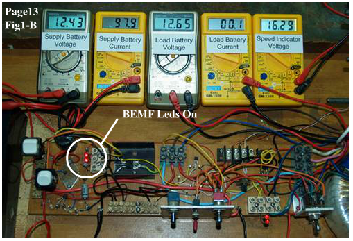
Fig1-B Shows the BEMF indicator Leds switched into circuit to show the bemf current flow. It also shows a loss of speed and increased supply current as a result.
|
||||||||||||||||||||||||||||||||||||||||||||||||||||||||||||||||||
|
||||||||||||||||||||||||||||||||||||||||||||||||||||||||||||||||||
|
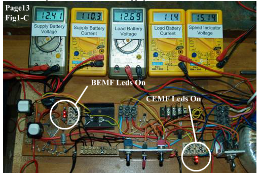
Fig1-C Shows the CEMF (flyback) circuit switched on with CEMF indicator Leds and load battery meters showing current flow and increased battery2 voltage. It also shows a further loss of speed and increased supply current as a result.
|
||||||||||||||||||||||||||||||||||||||||||||||||||||||||||||||||||
|
||||||||||||||||||||||||||||||||||||||||||||||||||||||||||||||||||
|
In the above photos, the main purpose was to show that bemf and cemf can be diverted and used at the same time. One does not cancel out the other. However they can affect one another. In Fig1-C above, the BEMF Leds are not quite as bright as they are in Fig1-B, because the cemf output load caused the rotor speed to fall. The bemf voltage is proportional to rotor speed, so a reduced speed yields a reduced voltage. In the summary table1 below, it can be seen that direct harvesting of the CEMF via a diode across the coil, is counter productive to running torque/speed in this particular motor. |
||||||||||||||||||||||||||||||||||||||||||||||||||||||||||||||||||
|
||||||||||||||||||||||||||||||||||||||||||||||||||||||||||||||||||
|
Judging from the experiments thus far, it would appear that the best thing to do with the bemf in this particular pulsed motor is simply to block it. But appearances like my assumptions are often misleading, and need challenging from time to time. A question I asked myself, "is this the best we can do with bemf – simply block it, or can it be manipulated to benefit like cemf". I showed on Page9 Fig27, the underlying principle of how harvesting cemf can be be either beneficial or counter productive to rotor speed depending on duty cycle, and coil impedance. |
||||||||||||||||||||||||||||||||||||||||||||||||||||||||||||||||||
|
|
||||||||||||||||||||||||||||||||||||||||||||||||||||||||||||||||||
|
I asked myself a few other questions too, before embarking on these next two circuits and experiments, Questions, such as "Can I utilize or neutralise the bemf without just blocking it ? Can I make this motor go faster, on less current, in some other way. Can I make it go faster than when the bemf is blocked ? Can I make this existing motor circuit harvest cemf, charge a battery and produce a torque increase instead of torque reduction at the same time ? Just like a well tuned impedance/duty cycle cemf circuit combination will sometimes do. Even though I can't significantly change it's duty cycle? Sometimes I drive myself mad with all the questions. Get off my back Hoptoads LOL. |
||||||||||||||||||||||||||||||||||||||||||||||||||||||||||||||||||
|
|
||||||||||||||||||||||||||||||||||||||||||||||||||||||||||||||||||
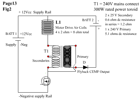
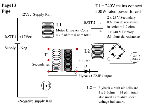
| Of course, nothing is more satisfying than an answer to a question, even if it's not necessarily the answer you'd been hoping for. I've had plenty of results I hadn't hoped for ! LOL. In the next two experiments, there is a dramatic shift in circuit design, operation and motor response characteristics. In some aspects the circuit/s seem counter intuitive in their operation. The first of these experiments introduces a transformer into the circuit in a novel manner. It is a 300W continuous power rated toroid transformer, made for the Australian market, with a primary winding intended for 240v mains connection, and two 25V ac secondary output windings designed to give continuous 12A x 25V capability. The circuit in Fig2 below, shows the toroid transformer included in the circuit. | ||||||||||||||||||||||||||||||||||||||||||||||||||||||||||||||||||
|
||||||||||||||||||||||||||||||||||||||||||||||||||||||||||||||||||
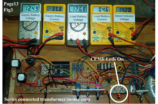
| Fig 3 – In the photo below, the transformer secondaries are connected in series with the motor coils, and the flyback is in series with the transformer primary as shown in Fig2 above. | ||||||||||||||||||||||||||||||||||||||||||||||||||||||||||||||||||
|
||||||||||||||||||||||||||||||||||||||||||||||||||||||||||||||||||
|
Fig3 above clearly shows a large drop in supply current, but also a significant drop in speed indicator voltage. It is charging the battery2, but at a reduced rate compared to direct diode harvesting (no transformer) as shown in the prior Fig 1-C. However, the relative speed decrease is much smaller than the relative decrease in supply current, indicating a better current versus rotor speed ratio, and thus a potentially higher efficiency. The battery2 is also being charged, and that's encouraging. Still, the speed indicator voltage is not greater than it would be without the transformer as shown in Fig1-A. But the results are encouraging. So what next.? To maximise the performance of the circuit by including another component! I think.? What ? won't that just add more losses?! The transformer should have increased circuit losses, which in turn should have lowered the relative efficiency, but the relative efficiency seems to contradict that. An extra component should just introduce more potential losses. Hmmnnn….Let's see. Fig4 below shows the voltage indicator coils, which are normally passive, meaning they are not connected to the supply, or contributing to the motor circuit in any way. They have now been connected in series with the flyback circuit, to perform two functions. 1.To continue giving a visual indication of relative rotor speed, and . 2. To allow the flyback current to flow through the voltage indicator coils (now flyback coils), enabling them to positively contribute to the motor circuit by increasing rotor torque. |
||||||||||||||||||||||||||||||||||||||||||||||||||||||||||||||||||
|
||||||||||||||||||||||||||||||||||||||||||||||||||||||||||||||||||
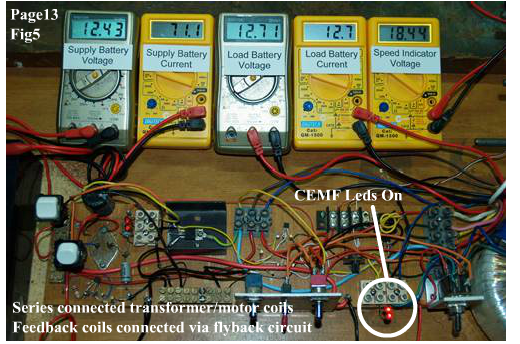
| Fig 5 below shows the results of series adding the voltage indicator coil to the flyback circuit. | ||||||||||||||||||||||||||||||||||||||||||||||||||||||||||||||||||
|
||||||||||||||||||||||||||||||||||||||||||||||||||||||||||||||||||
| Table 2 below combines the data from table1 with the data from Fig3 anf Fig5 above, I can happily say yes to most of my previous questions. With this particular motor's air core coils and transformer arrangement, I can manipulate the cemf more efficiently in order to 1: increase motor speed (running torque), to a greater speed than an unloaded motor. 2: charge a battery load at the same time with cemf . 3: decrease supply current while increasing speed | ||||||||||||||||||||||||||||||||||||||||||||||||||||||||||||||||||
|
||||||||||||||||||||||||||||||||||||||||||||||||||||||||||||||||||
|
In the next experiments the transformer and flyback coil configurations will not incorporate a blocking diode in the main supply circuit, and all the experiments will not include Leds in the circuits as indicators. See Page14 for more information and additional experimental data. |